Mission logs, plots, and models
Explore recorded ArduCopter, ArduPlane, and ArduRover missions below. Drag a time slider, click the lower plot, or press Replay. Each panel has its own controls. The gray track shows the complete route, the blue trace advances with time, and the red marker shows the selected sample. Numbered points are the uploaded mission waypoints.
The Copter and Rover recordings use this checkout’s pinned compiler and array-based models. Their downloadable summaries record source revisions and model hashes. Plane is a historical recording: the current three-wheel model is included in the repository, but its FMI export awaits compiler event support.
| Vehicle | Completion check | Model status |
|---|---|---|
| ArduCopter | Final mission item, low altitude, and firmware ON_GROUND | Current model, rerun successfully |
| ArduRover | Final waypoint 4 reached | Current model, rerun successfully |
| ArduPlane | Waypoint 11 reached while airborne | Historical recording; current model not flight-validated |
The console logs confirm completion independently of the trajectory plot.
ArduCopter
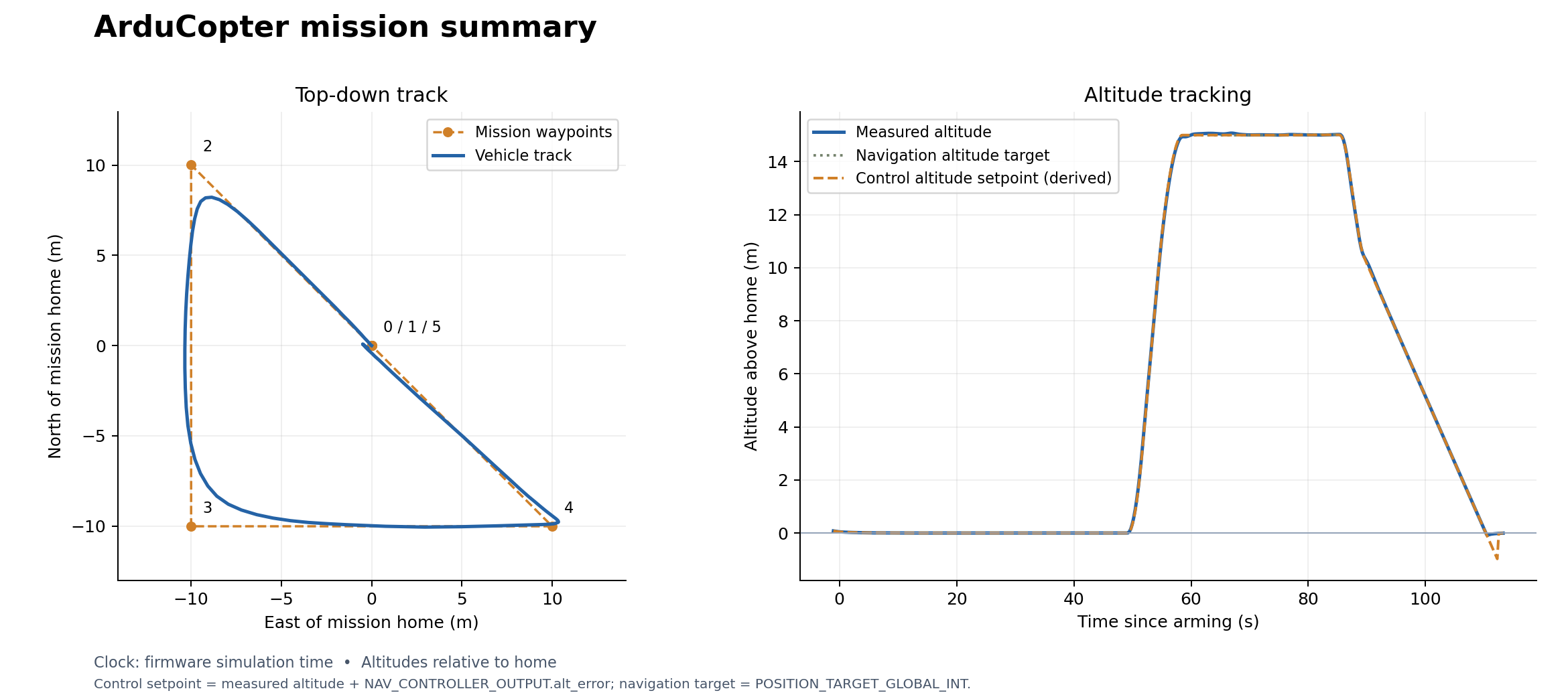
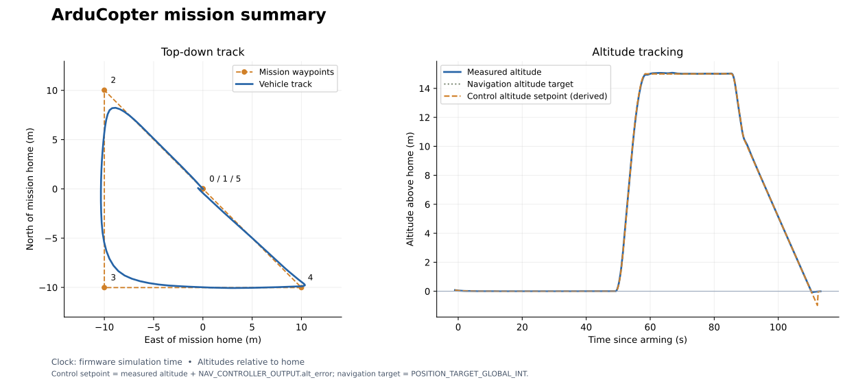
The 500 mm quadrotor takes off, visits its waypoints, and lands. Compare measured altitude with the derived controller setpoint using the checkbox.
Static Copter trajectory and altitude figure
SVG · CSV · MAVLink log · Console log · Mission file · Run summary
Model used for this run: FastDyn.Copter
within FastDyn;

model Copter
  parameter Real mass = 2.5644001 "Gazebo gs_drone equivalent mass [kg]";
  parameter Real inertia[3,3] = diagonal({0.02601237985, 0.02590943825, 0.045571756801})
    "Inertia about the CG in body FLU [kg*m^2]";
  parameter Real Ct = 8.54858e-6 "Thrust coefficient [N/(rad/s)^2]";
  parameter Real Cm = 0.016 "Rotor torque/thrust ratio [m]";
  parameter Real arm_length = 0.25 "Arm length [m]";
  parameter Real Cl_p = -0.2 "Rolling moment coefficient per roll rate";
  parameter Real Cm_q = -0.2 "Pitching moment coefficient per pitch rate";
  parameter Real Cn_r = -0.1 "Yawing moment coefficient per yaw rate";
  parameter Real tau_up = 0.0125 "Motor spin-up time constant [s]";
  parameter Real tau_down = 0.025 "Motor spin-down time constant [s]";
  parameter Real body_area = 0.1 "Reference area for rate damping [m^2]";
  parameter Real drag_area[3] = {0.06, 0.08, 0.12} "Body drag areas [m^2]";
  parameter Real linear_drag[3] = {0.12, 0.12, 0.18} "Body linear drag [N*s/m]";
  parameter Real leg_x = 0.17 "Ground contact X offset [m]";
  parameter Real leg_y = 0.17 "Ground contact Y offset [m]";
  parameter Real leg_z = -0.10 "Ground contact Z offset in body FLU [m]";
  parameter Real ground_k = 3000 "Contact stiffness [N/m]";
  parameter Real ground_c = 150 "Contact normal damping [N*s/m]";
  parameter Real ground_tangent_c = 25 "Contact tangential damping [N*s/m]";

  FastDyn.QuadrotorWithExternalWrench plant(
    external_force_b = {0, 0, 0},
    external_moment_b = {0, 0, 0},
    ground_z = 0.0,
    vehicle_mass = mass,
    J = inertia,
    gravity = 9.8,
    mag_world_enu = {0.21, 0, -0.45},
    Ct = Ct,
    Cm = Cm,
    arm_length = arm_length,
    Cl_p = Cl_p,
    Cm_q = Cm_q,
    Cn_r = Cn_r,
    tau_up = tau_up,
    tau_down = tau_down,
    S = body_area,
    CdA = drag_area,
    linear_drag = linear_drag,
    leg_x = leg_x,
    leg_y = leg_y,
    leg_z = leg_z,
    ground_k = ground_k,
    ground_c = ground_c,
    ground_tangent_c = ground_tangent_c);

  parameter Real pwm_min = 1100.0 "Minimum motor PWM used by the Gazebo gs_drone ArduPilot control block";
  parameter Real pwm_max = 1900.0 "Maximum motor PWM used by the Gazebo gs_drone ArduPilot control block";
  parameter Real omega_min = 0.0 "Motor speed at minimum PWM [rad/s]";
  parameter Real omega_max = 1300.0 "Aerodynamic motor speed at maximum PWM [rad/s]";
  parameter Real lat0 = 40.414929 "Reference latitude [deg]";
  parameter Real lon0 = -86.932387 "Reference longitude [deg]";
  parameter Real ground_alt_wgs84 = 149.0 "WGS84 ellipsoid altitude of the local ground collision plane [m]";
  parameter Real accel_bias[3] = {0, 0, 0} "Accelerometer bias [m/s^2]";
  parameter Real gyro_bias[3] = {0, 0, 0} "Gyroscope bias [rad/s]";
  parameter Real mag_bias[3] = {0, 0, 0} "Magnetometer bias [Gauss]";
  parameter Real gps_bias[3] = {0, 0, 0} "GPS bias N/E/altitude [m]";
  parameter Real baro_alt_bias = 0.0 "Barometer relative altitude bias [m]";
  parameter Real earth_radius_m = 6378137.0 "Spherical Earth radius used for local geodetic conversion [m]";
  parameter Real pi = 3.141592653589793;

  input Real pwm[4](start = {1000, 1000, 1000, 1000}) "Motor PWM commands";

  output Real accel[3] "Body FRD accelerometer [m/s^2]";
  output Real gyro[3] "Body FRD gyroscope [rad/s]";
  output Real mag[3] "Body FRD magnetometer [Gauss]";
  output Real gps[3] "GPS latitude, longitude, altitude";
  output Real vel_ned[3] "GPS velocity NED [m/s]";
  output Real yaw_deg "Yaw [deg]";
  output Real baro_altitude_m "Barometer relative altitude [m]";
  output Real baro_pressure_pa "Barometer pressure [Pa]";
  output Real baro_temperature_c "Barometer temperature [degC]";
  output Real baro_climb_rate_mps "Barometer climb rate [m/s]";
  output Real motor_cmd[4] "Motor commands after PWM scaling [rad/s]";

protected
  Real pwm_span;
  Real pwm_norm[4];
  Real gps_lat_lon[2];
  Real geodetic_origin[3] "Reference latitude, longitude, and Earth radius";
  Real yaw_rad;

equation
  pwm_span = pwm_max - pwm_min;

  for i in 1:4 loop
    pwm_norm[i] = min(1.0, max(0.0, (pwm[i] - pwm_min) / pwm_span));
    motor_cmd[i] = omega_min + (omega_max - omega_min) * pwm_norm[i];
    plant.omega_cmd[i] = motor_cmd[i];
  end for;

  accel = {plant.accel[1], -plant.accel[2], -plant.accel[3]} + accel_bias;
  gyro = {plant.gyro[1], -plant.gyro[2], -plant.gyro[3]} + gyro_bias;
  mag = {plant.mag[1], -plant.mag[2], -plant.mag[3]} + mag_bias;

  // Avoid collisions between the caller parameters and the function locals
  // during function projection in the pinned Rumoca compiler.
  geodetic_origin = {lat0, lon0, earth_radius_m};
  gps_lat_lon = Geodesy.localNorthEastToLatLon(
    geodetic_origin[1],
    geodetic_origin[2],
    plant.p[1] + gps_bias[1],
    -plant.p[2] + gps_bias[2],
    geodetic_origin[3]);
  gps[1] = gps_lat_lon[1];
  gps[2] = gps_lat_lon[2];
  gps[3] = ground_alt_wgs84 + plant.p[3] + gps_bias[3];

  vel_ned[1] = plant.v_w[1];
  vel_ned[2] = -plant.v_w[2];
  vel_ned[3] = -plant.v_w[3];

  yaw_rad = atan2(2.0 * (plant.q[1] * plant.q[4] + plant.q[2] * plant.q[3]),
                  1.0 - 2.0 * (plant.q[3] * plant.q[3] + plant.q[4] * plant.q[4]));
  yaw_deg = -yaw_rad * 180.0 / pi;

  baro_altitude_m = plant.p[3] + baro_alt_bias;
  baro_temperature_c = 15.0 - 0.0065 * (ground_alt_wgs84 + baro_altitude_m);
  baro_pressure_pa = 101325.0 * (1.0 - 2.25577e-5 * (ground_alt_wgs84 + baro_altitude_m)) ^ 5.25588;
  baro_climb_rate_mps = plant.v_w[3];
end Copter;
The wrapper maps four PWM commands to motor speeds and connects
Vehicles.Templates.QuadrotorPlant to FastDyn’s sensor interface. See the
model walkthrough for its array parameters and equations.
fastdyn-config --base configs/copter462.toml --output out/copter.toml
fastdyn run -c out/copter.toml -o out/copter/work
ArduPlane
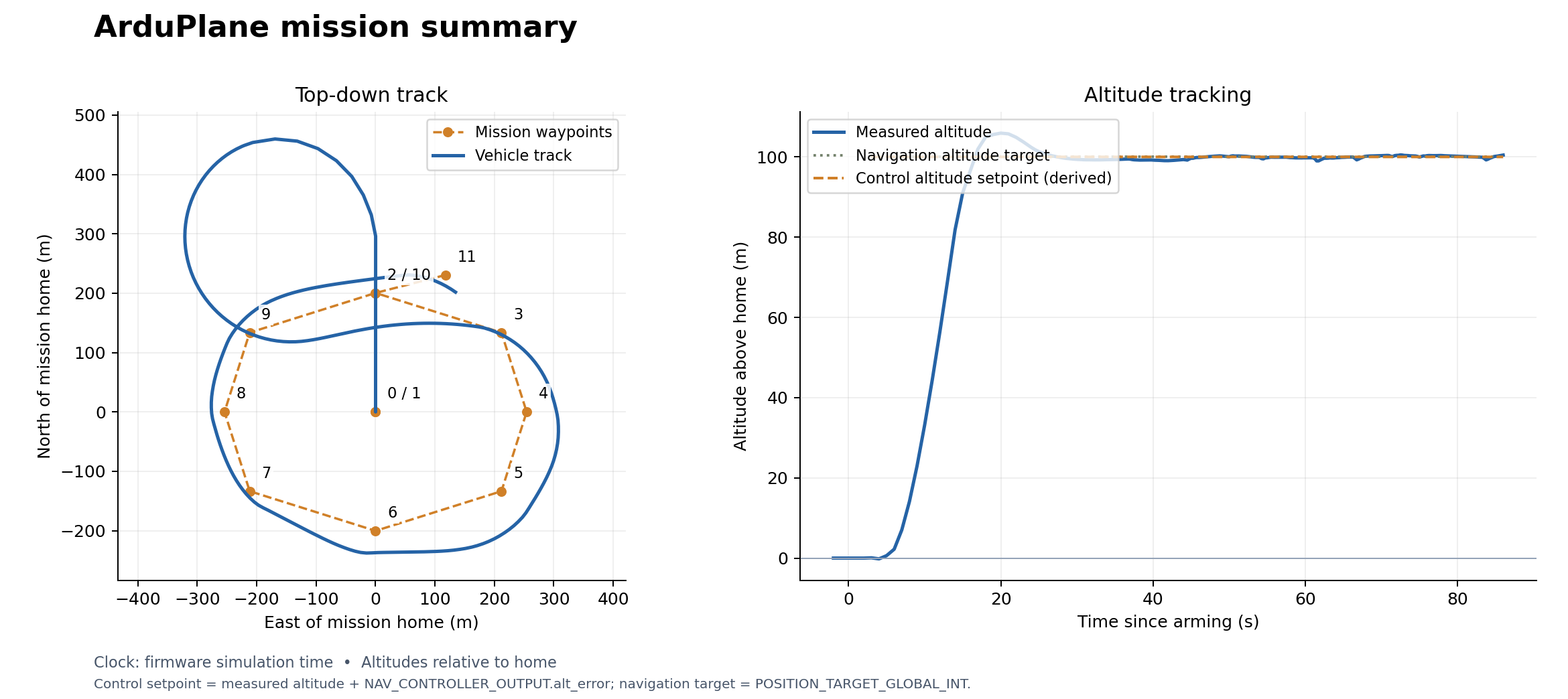
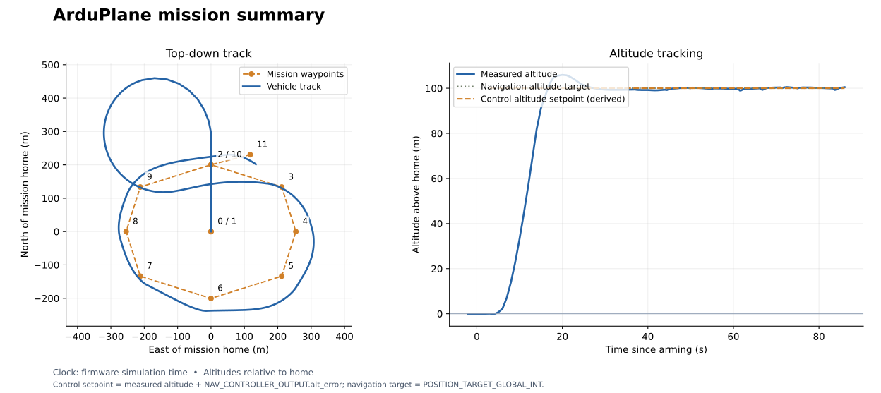
Historical result: the fixed-wing aircraft starts stationary, takes off to 100 m, and flies a waypoint circuit. This run ends after waypoint 11 is reached while the plane is still airborne. It demonstrates takeoff and navigation; automatic landing has not been tested by this mission.
Static Plane trajectory and altitude figure
SVG · CSV · MAVLink log · Console log · Mission file · Run summary
Model used for this run: FastDyn.Plane
within FastDyn;

model Plane
  // Start stationary on the ground while the firmware initializes its sensors.
  RigidBody.Examples.FixedWingPlant plant(
    p_start = {0, 0, 0}, v_b_start = {0, 0, 0},
    // The plant defines alpha from FLU vertical velocity, so nose-up flight
    // has negative alpha. Lift must increase as that angle becomes negative.
    CL_alpha = -4.2);

  parameter Real pwm_min = 1000.0 "Minimum PWM";
  parameter Real pwm_trim = 1500.0 "Neutral PWM";
  parameter Real pwm_max = 2000.0 "Maximum PWM";
  parameter Real Cn_beta = 0.10 "Yaw stability coefficient per FLU sideslip [1/rad]";
  parameter Real lat0 = 40.414929 "Reference latitude [deg]";
  parameter Real lon0 = -86.932387 "Reference longitude [deg]";
  parameter Real ground_alt_wgs84 = 149.0 "WGS84 ellipsoid altitude of the local ground plane [m]";
  parameter Real accel_bias[3] = {0, 0, 0} "Accelerometer bias [m/s^2]";
  parameter Real gyro_bias[3] = {0, 0, 0} "Gyroscope bias [rad/s]";
  parameter Real mag_bias[3] = {0, 0, 0} "Magnetometer bias [Gauss]";
  parameter Real gps_bias[3] = {0, 0, 0} "GPS bias N/E/altitude [m]";
  parameter Real baro_alt_bias = 0.0 "Barometer relative altitude bias [m]";
  parameter Real earth_radius_m = 6378137.0 "Spherical Earth radius used for local geodetic conversion [m]";
  parameter Real pi = 3.141592653589793;

  input Real pwm[4](start = {1500, 1500, 1000, 1500}) "Servo PWM commands";

  output Real accel[3] "Body FRD accelerometer [m/s^2]";
  output Real gyro[3] "Body FRD gyroscope [rad/s]";
  output Real mag[3] "Body FRD magnetometer [Gauss]";
  output Real gps[3] "GPS latitude, longitude, altitude";
  output Real vel_ned[3] "GPS velocity NED [m/s]";
  output Real yaw_deg "Yaw [deg]";
  output Real baro_altitude_m "Barometer relative altitude [m]";
  output Real baro_pressure_pa "Barometer pressure [Pa]";
  output Real baro_temperature_c "Barometer temperature [degC]";
  output Real baro_climb_rate_mps "Barometer climb rate [m/s]";
  output Real motor_cmd[4] "Normalized aileron/elevator/throttle/rudder commands";

protected
  Real aileron;
  Real elevator;
  Real throttle;
  Real rudder;
  Real gps_lat_lon[2];
  Real geodetic_origin[3] "Reference latitude, longitude, and Earth radius";
  Real yaw_rad;

equation
  aileron = min(1.0, max(-1.0, (pwm[1] - pwm_trim) / (pwm_max - pwm_trim)));
  elevator = min(1.0, max(-1.0, (pwm[2] - pwm_trim) / (pwm_max - pwm_trim)));
  throttle = min(1.0, max(0.0, (pwm[3] - pwm_min) / (pwm_max - pwm_min)));
  rudder = min(1.0, max(-1.0, (pwm[4] - pwm_trim) / (pwm_max - pwm_trim)));

  plant.aileron = aileron;
  plant.elevator = elevator;
  plant.throttle = throttle;
  // The upstream plant has no vertical-tail sideslip moment. Include that
  // moment through its rudder term so a banked aircraft turns into its
  // velocity vector instead of settling into a constant-heading sideslip.
  plant.rudder = rudder + Cn_beta / plant.Cn_rudder * atan2(
    plant.v_b[2], sqrt(plant.v_b[1] ^ 2 + plant.v_b[3] ^ 2 + 0.01));

  accel = plant.accel + accel_bias;
  gyro = plant.gyro + gyro_bias;
  mag = plant.mag + mag_bias;

  // Avoid collisions between the caller parameters and the function locals
  // during function projection in the pinned Rumoca compiler.
  geodetic_origin = {lat0, lon0, earth_radius_m};
  gps_lat_lon = Geodesy.localNorthEastToLatLon(
    geodetic_origin[1],
    geodetic_origin[2],
    plant.p[1] + gps_bias[1],
    -plant.p[2] + gps_bias[2],
    geodetic_origin[3]);
  gps[1] = gps_lat_lon[1];
  gps[2] = gps_lat_lon[2];
  gps[3] = ground_alt_wgs84 + plant.p[3] + gps_bias[3];

  vel_ned[1] = plant.v_w[1];
  vel_ned[2] = -plant.v_w[2];
  vel_ned[3] = -plant.v_w[3];

  yaw_rad = atan2(2.0 * (plant.q[1] * plant.q[4] + plant.q[2] * plant.q[3]),
                  1.0 - 2.0 * (plant.q[3] * plant.q[3] + plant.q[4] * plant.q[4]));
  yaw_deg = -yaw_rad * 180.0 / pi;

  baro_altitude_m = plant.p[3] + baro_alt_bias;
  baro_temperature_c = 15.0 - 0.0065 * (ground_alt_wgs84 + baro_altitude_m);
  baro_pressure_pa = 101325.0 * (1.0 - 2.25577e-5 * (ground_alt_wgs84 + baro_altitude_m)) ^ 5.25588;
  baro_climb_rate_mps = plant.v_w[3];
  motor_cmd = {aileron, elevator, throttle, rudder};
end Plane;
The archived wrapper uses an earlier plant with a single ground contact. Its exact source and revision are preserved in the downloads above; it does not represent the new three-wheel landing gear.
The current Plane model and configuration instantiate
Vehicles.Templates.FixedWingPlant with two main wheels and a tailwheel.
The pinned compiler lowers this model but rejects FMI export of its contact
events. CI checks that boundary explicitly. Wait for event support and a new
flight validation before using this model for an ArduPlane exercise.
ArduRover
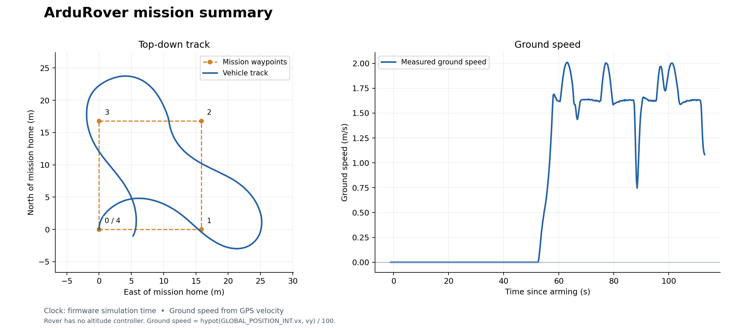
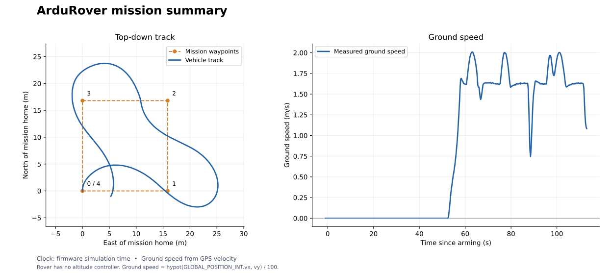
The rover follows four waypoints around a rectangle. The lower plot shows
ground speed, derived from the horizontal GPS velocity, because Rover
has no altitude controller. This recording’s home-altitude reference
was zero while its GPS altitude was near 149 m; its relative_alt field must
not be interpreted as the rover hovering 149 m above the ground.
Static Rover trajectory and speed figure
SVG · CSV · MAVLink log · Console log · Mission file · Run summary
Model used for this run: FastDyn.Rover
within FastDyn;

model Rover
  RigidBody.Examples.RoverPlant plant(mag_world_enu = {0.21, 0, -0.45});

  parameter Real pwm_min = 1000.0 "Minimum PWM";
  parameter Real pwm_trim = 1500.0 "Neutral PWM";
  parameter Real pwm_max = 2000.0 "Maximum PWM";
  parameter Real lat0 = 40.414929 "Reference latitude [deg]";
  parameter Real lon0 = -86.932387 "Reference longitude [deg]";
  parameter Real ground_alt_wgs84 = 149.0 "WGS84 ellipsoid altitude of the local ground plane [m]";
  parameter Real accel_bias[3] = {0, 0, 0} "Accelerometer bias [m/s^2]";
  parameter Real gyro_bias[3] = {0, 0, 0} "Gyroscope bias [rad/s]";
  parameter Real mag_bias[3] = {0, 0, 0} "Magnetometer bias [Gauss]";
  parameter Real gps_bias[3] = {0, 0, 0} "GPS bias N/E/altitude [m]";
  parameter Real baro_alt_bias = 0.0 "Barometer relative altitude bias [m]";
  parameter Real earth_radius_m = 6378137.0 "Spherical Earth radius used for local geodetic conversion [m]";
  parameter Real pi = 3.141592653589793;

  input Real pwm[4](start = {1500, 1500, 1500, 1500}) "Servo PWM commands";

  output Real accel[3] "Body FRD accelerometer [m/s^2]";
  output Real gyro[3] "Body FRD gyroscope [rad/s]";
  output Real mag[3] "Body FRD magnetometer [Gauss]";
  output Real gps[3] "GPS latitude, longitude, altitude";
  output Real vel_ned[3] "GPS velocity NED [m/s]";
  output Real yaw_deg "Yaw [deg]";
  output Real baro_altitude_m "Barometer relative altitude [m]";
  output Real baro_pressure_pa "Barometer pressure [Pa]";
  output Real baro_temperature_c "Barometer temperature [degC]";
  output Real baro_climb_rate_mps "Barometer climb rate [m/s]";
  output Real motor_cmd[4] "Normalized steering/throttle commands";

protected
  Real steering;
  Real throttle;
  Real gps_lat_lon[2];
  Real geodetic_origin[3] "Reference latitude, longitude, and Earth radius";
  Real yaw_rad;

equation
  steering = min(1.0, max(-1.0, (pwm[1] - pwm_trim) / (pwm_max - pwm_trim)));
  throttle = min(1.0, max(-1.0, (pwm[3] - pwm_trim) / (pwm_max - pwm_trim)));
  plant.steering = steering;
  plant.throttle = throttle;

  accel = {plant.accel[1], -plant.accel[2], -plant.accel[3]} + accel_bias;
  gyro = {plant.gyro[1], -plant.gyro[2], -plant.gyro[3]} + gyro_bias;
  mag = {plant.mag[1], -plant.mag[2], -plant.mag[3]} + mag_bias;

  // Avoid collisions between the caller parameters and the function locals
  // during function projection in the pinned Rumoca compiler.
  geodetic_origin = {lat0, lon0, earth_radius_m};
  gps_lat_lon = Geodesy.localNorthEastToLatLon(
    geodetic_origin[1],
    geodetic_origin[2],
    plant.p[1] + gps_bias[1],
    -plant.p[2] + gps_bias[2],
    geodetic_origin[3]);
  gps[1] = gps_lat_lon[1];
  gps[2] = gps_lat_lon[2];
  gps[3] = ground_alt_wgs84 + plant.p[3] + gps_bias[3];

  vel_ned[1] = plant.v_w[1];
  vel_ned[2] = -plant.v_w[2];
  vel_ned[3] = -plant.v_w[3];

  yaw_rad = atan2(2.0 * (plant.q[1] * plant.q[4] + plant.q[2] * plant.q[3]),
                  1.0 - 2.0 * (plant.q[3] * plant.q[3] + plant.q[4] * plant.q[4]));
  yaw_deg = -yaw_rad * 180.0 / pi;

  baro_altitude_m = plant.p[3] + baro_alt_bias;
  baro_temperature_c = 15.0 - 0.0065 * (ground_alt_wgs84 + baro_altitude_m);
  baro_pressure_pa = 101325.0 * (1.0 - 2.25577e-5 * (ground_alt_wgs84 + baro_altitude_m)) ^ 5.25588;
  baro_climb_rate_mps = plant.v_w[3];
  motor_cmd = {steering, throttle, plant.v_b[1], plant.omega[3]};
end Rover;
Steering comes from PWM channel 1 and signed throttle from channel 3. The
wrapper connects them to Vehicles.Templates.RoverPlant and exposes the same
sensor interface to the firmware. See the complete Rover TOML.
fastdyn-config --base configs/rover462.toml --output out/rover.toml
fastdyn run -c out/rover.toml -o out/rover/work
Run the vehicle examples one at a time; their default ports are shared.
Rebuild the reports from these recordings
The book includes the original telemetry and uploaded waypoint files, so you can regenerate the figures without rerunning a simulation. In your chosen environment, from the repository root:
python -m fastdyn.mission_report --vehicle copter \
  --log docs/book/assets/baseline-mission.tlog \
  --mission docs/book/assets/baseline-mission.waypoints \
  --output out/reports/copter.png --require-setpoint

python -m fastdyn.mission_report --vehicle plane \
  --log docs/book/assets/plane-mission.tlog \
  --mission docs/book/assets/plane-mission.waypoints \
  --output out/reports/plane.png --require-setpoint

python -m fastdyn.mission_report --vehicle rover \
  --log docs/book/assets/rover-mission.tlog \
  --mission docs/book/assets/rover-mission.waypoints \
  --output out/reports/rover.png
Each command prints a JSON summary and writes PNG, SVG, CSV, and JSON files
under out/reports/. Plane and Rover finish at mission items 11 and 4. Copter can reset its mission cursor after landing; use the console completion marker and on-ground telemetry as the success check.
--require-setpoint checks that controller altitude telemetry was recorded;
it is used for Copter and Plane.
For these Copter and fixed-wing Plane runs, the derived altitude setpoint is
GLOBAL_POSITION_INT.relative_alt / 1000 + NAV_CONTROLLER_OUTPUT.alt_error.
Position and controller messages are paired by firmware time, so the estimate
can show small timing errors. POSITION_TARGET_GLOBAL_INT, when present,
provides a separate navigation target; the static plots include it after
conversion from absolute altitude using home altitude. It can differ from the
controller’s intermediate target during takeoff or climb. Rover sends zero for
alt_error; the report does not turn that placeholder into an altitude setpoint.
Record your own run
fastdyn-config configures MAVProxy to write out/<vehicle>/mission.tlog beside
the generated TOML’s other run files. Capture console output as well:
fastdyn run -c out/copter.toml -o out/copter/work > out/copter/console.log 2>&1
Use your new .tlog and the waypoint file actually uploaded to the vehicle as
the report inputs. Select --vehicle plane, --vehicle rover, or --vehicle copter
to get the correct title and plotted quantity.
CI runs complete Copter and Rover missions and reports the pending Plane export support separately. Download mission-report from a successful CI run for the telemetry, console logs, and summary plots. ci-logs contains additional build and runtime diagnostics.