FastDyn
FastDyn · Firmware meets physics
Real firmware.
Your vehicle model.
Connect embedded firmware to a Modelica plant. Change the physics, tune the controller, and follow the results from sensor to trajectory.
FastDyn runs embedded firmware in a configurable QEMU environment. A TOML file describes the CPU, memory map, firmware, peripherals, instrumentation, and any external physics model. You can inspect firmware behavior, supply virtual devices, connect selected hardware, and automate repeatable experiments.
Follow the signals
flowchart LR
    config["TOML<br/>Configuration"] --> firmware["Firmware<br/>in QEMU"]
    firmware <-->|"Device access"| drivers["FastDyn<br/>Drivers"]
    drivers <-->|"PWM · Sensors"| plant["Modelica<br/>Physics model"]
    firmware <-->|"MAVLink"| tools["Mission commands<br/>Logs and plots"]
The Rumoca examples preserve the firmware’s sensor and actuator driver path. Fidelity comes from the emulated firmware, peripheral behavior, timing, and plant working together. A detailed firmware simulation still needs a suitable, validated physical model; an idealized plant does not reproduce every effect of a real airframe.
To preview this book, run mdbook serve docs --open from your chosen development
environment and open http://localhost:3000. For a lightweight docs-only setup,
see preview and publish the book.
Architecture and first steps
FastDyn starts with an executable firmware image and a description of its board. The firmware executes in patched QEMU. FastDyn’s plugin routes device accesses through the models selected in TOML and applies configured virtuals, modifiers, and instrumentation.
flowchart TD
    config["TOML: CPU, memory, devices, tools"] --> qemu["Firmware executing in QEMU"]
    qemu <-->|"Peripheral access"| plugin["FastDyn plugin"]
    plugin --> virtual["Virtual device models"]
    plugin --> hardware["Selected real hardware"]
    plugin <-->|"Sensors and actuators"| physics["Optional physics backend"]
    qemu --> trace["Instrumentation and run artifacts"]
1. Inspect a configuration
After choosing your environment, from the repository root:
fastdyn run --help
Expect help beginning with Runs the firmware on QEMU using the passed config file, including required --config and optional --work-dir arguments.
Your chosen environment supplies tools; the TOML selects the firmware and simulation.
Read configs/bare_bones.toml for the configuration shape, then choose a
configuration matching your actual firmware. A starter is not automatically a
correct board model. Review the CPU, memory addresses, vector table, device
ranges, interrupts, and clock assumptions.
2. Run a configured target
The general command is:
fastdyn run -c <your-config.toml> -o <your-work-directory>
The angle-bracket paths are placeholders. For an executable example with the included firmware, use the Rumoca first mission.
3. Inspect the run
The work directory contains generated device routing and virtual/modifier
rules, plus enabled instrumentation output. Compare those generated rules with
your intended configuration before interpreting a failed boot as a firmware
bug. fastdyn help opens the configuration-help browser.
For other hardware and native builds, follow README.md and setup.sh --help.
The supplied simulation environment currently targets x86-64 Linux.
Choose your environment
Choose one setup below. Nix, Docker, and a manual installation provide the
same FastDyn commands. The tutorial then uses fastdyn-config, fastdyn, and
python; simulation choices belong in TOML files.
The supplied simulation environment targets x86-64 Linux. Prepare it before the one-hour walkthrough: the first compiler and QEMU builds can take much longer than an exercise. Run all tutorial commands from the FastDyn repository root.
Get the sources
Clone the repository’s main branch:
git clone --branch main https://github.com/jgoppert/FastDyn.git
cd FastDyn
If you already have this checkout, use it. From the repository root, initialize the pinned compiler, model library, and peripheral descriptions:
git submodule update --init --depth 1 \
  third_party/common/rumoca \
  third_party/common/modelica_models \
  third_party/common/cmsis-svd-data
The source revisions are recorded in Git and flake.lock. Ordinary output goes
under the ignored out/ directory.
Option A: Nix
Follow the official Nix installation guide.
Nix is a package manager; it does not require installing NixOS. Read the
flake introduction for how flake.nix
and flake.lock describe and pin the environment.
Enable nix-command and flakes as described in the
Nix configuration reference.
For a standard Linux installation, add this to ~/.config/nix/nix.conf,
preserving existing settings:
extra-experimental-features = nix-command flakes
On NixOS, use nix.settings.experimental-features = [ "nix-command" "flakes" ];
in the system configuration instead. Skip this if your installer enabled both.
nix --version
nix flake metadata --no-write-lock-file
nix develop
Expect the flake description FastDyn development environment and
documentation, then a shell with Python, the patched QEMU, FastDyn’s plugin,
Rumoca, build tools, and mdBook. Later sessions reuse built dependencies.
Exit this shell with exit.
Option B: Docker
Install Docker Engine. Use the
published image from the repository containing this book. For jgoppert/FastDyn:
docker pull ghcr.io/jgoppert/fastdyn/dev:latest
docker run --rm -it --user "$(id -u):$(id -g)" \
  --volume "$PWD:/workspace" --publish 5000:5000 --publish 3000:3000 \
  ghcr.io/jgoppert/fastdyn/dev:latest
You are now at /workspace, with the checkout mounted and tools available.
Files created under out/ belong to your host user. Port 5000 exposes the live
mission viewer; port 3000 is for an optional documentation server. Run the
simulation and its helpers together inside the container.
If you have a locally built image archive instead, load it and start the same environment:
docker load --input fastdyn-dev.tar.gz
docker run --rm -it --user "$(id -u):$(id -g)" \
  --volume "$PWD:/workspace" --publish 5000:5000 --publish 3000:3000 \
  fastdyn-dev:local
You need only Docker to load and use that archive. See
build and share the Docker environment for the Nix build,
archive distribution, and container commands. In another repository, the
image address is ghcr.io/<owner>/<repository>/dev:latest, all lowercase.
Option C: install and build the dependencies
The repository’s native setup supports Ubuntu 24.04. Install its build tools:
sudo apt-get update
sudo apt-get install -y \
  build-essential cmake device-tree-compiler git libexpat1-dev libfdt-dev \
  libglib2.0-dev libpixman-1-dev libudev-dev lsof meson ninja-build pkg-config \
  python3-dev python3-venv universal-ctags zlib1g-dev
Install Rust using rustup’s instructions
if cargo is not already available. Then build and enter the Python environment:
source ./setup.sh --build-qemu --with-rumoca --skip-optifuzz
This builds the patched QEMU and plugin, installs Python dependencies and the
fastdyn / fastdyn-config commands, and builds the pinned native Rumoca.
For later terminals, run source fastdyn-env/bin/activate.
Nix, Docker, and the native setup use the same pinned Rumoca compiler. The
repository’s Git submodule and flake.lock record its exact revision.
Check the common commands
Inside whichever environment you chose:
fastdyn run --help
fastdyn-config --help
rumoca --version
python -c "import fastdyn, fmpy, pymavlink; print('Python dependencies available')"
Expect command help, rumoca 0.10.0, and Python dependencies available.
Continue to architecture and first steps or the
first Rumoca mission.
Build and share the Docker environment with Nix
Use Nix to build the development environment once, then distribute it as a
Docker image. The machine building the image needs Nix; a machine running the
image needs only Docker. This is the same environment as nix develop, with
the compilers, patched QEMU, FastDyn tools, Python dependencies, and mdBook.
flowchart TD
    pins["flake.nix + flake.lock"] --> shell["nix develop<br/>Local development shell"]
    pins --> build["nix build .#devContainer"]
    build --> archive["Docker image archive"]
    archive --> local["docker load<br/>Use or share locally"]
    archive --> registry["GitHub Actions<br/>Publish to GHCR"]
    registry --> pull["docker pull<br/>No Nix installation needed"]
    local --> run["docker run<br/>Mount the FastDyn checkout"]
    pull --> run
The image targets Linux x86-64 (linux/amd64). It contains the tools;
your source checkout, TOML files, models, and results come from a mounted
directory. It is a development and simulation image, not a preconfigured
long-running simulation service.
Build and load the image
Follow the Nix setup and install Docker Engine. From the FastDyn root:
nix build .#devContainer --out-link out/dev-container
docker load --input out/dev-container
The first command creates a link to a compressed image archive in the Nix
store. The second should print Loaded image: fastdyn-dev:local. It does not
publish anything. The first build can take time; later builds reuse unchanged
Nix dependencies. nix/dev-container.nix derives the image from the development
shell with dockerTools.streamNixShellImage, so there is no second package list
or Dockerfile to maintain.
Check the loaded tools:
docker run --rm fastdyn-dev:local bash -c \
  'rumoca --version && fastdyn --help && mdbook --version'
Expect Rumoca 0.10.0, FastDyn command help, and mdBook 0.5.2.
Run against your checkout
Initialize the source submodules, then enter:
docker run --rm -it --user "$(id -u):$(id -g)" \
  --volume "$PWD:/workspace" --publish 5000:5000 --publish 3000:3000 \
  fastdyn-dev:local
The shell opens at /workspace. The user mapping keeps generated files owned
by your host user. Run fastdyn-config, fastdyn, and python here just as in
the other environments. Keep simulation settings in TOML; the container does
not need environment variables to select a model or mission.
After creating a run configuration inside this environment, you can also run
it directly from the host. For example, the first mission
creates out/copter.toml:
docker run --rm --user "$(id -u):$(id -g)" \
  --volume "$PWD:/workspace" --publish 5000:5000 fastdyn-dev:local \
  fastdyn run -c out/copter.toml -o out/copter/work
Regenerate run configurations inside the container when moving from another
machine or environment: generated tool and socket paths describe that runtime.
Results under out/ remain on the host after --rm removes the container.
Run one vehicle at a time with the supplied port assignments.
To view this book from the container:
docker run --rm -it --user "$(id -u):$(id -g)" \
  --volume "$PWD:/workspace" --publish 3000:3000 fastdyn-dev:local \
  mdbook serve docs --hostname 0.0.0.0
Open http://localhost:3000 on the host. Binding to 0.0.0.0 inside the
container allows Docker’s published port to reach mdBook.
Share an archive or use GHCR
To share the built image without a registry, copy the actual archive rather than the Nix store symlink:
cp --dereference out/dev-container out/fastdyn-dev.tar.gz
On the receiving machine:
docker load --input fastdyn-dev.tar.gz
Use the docker run commands above with a checkout of the same FastDyn revision.
The publishing workflow builds
and checks the image on pull requests and publishes it on pushes to main.
Same-repository PRs also publish preview tags such as pr-1; fork PRs do not publish.
To use the published image instead, run:
docker pull ghcr.io/jgoppert/fastdyn/dev:latest
Replace fastdyn-dev:local in the run commands with that image name. For a
repeatable tutorial, use the published sha-<full-commit> tag and check out the
matching commit instead of following latest. In another repository, the
workflow publishes to ghcr.io/<owner>/<repository>/dev, all lowercase.
The build and publication steps are automatic; Pages enablement and package
visibility are the repository settings described in the contributing chapter.
Running FastDyn
Slide: Run a firmware from one configuration
FastDyn turns a firmware ELF and one TOML configuration into a QEMU run.
fastdyn run -c configs/target.toml -o fastdyn_work
-c/--configis required: it selects the board, CPU, memory, firmware, device routing, virtuals, and enabled run-wide plugins.-o/--work-dirselects where FastDyn writes run artifacts. It defaults to./fastdyn_work; give each experiment its own directory.- FastDyn prepares enabled plugins, resolves symbols and trigger addresses, writes generated virtual/modifier rules, prepares RAM backing, builds a configured FMU when applicable, then launches QEMU.
Slide: A practical first run
# Optional: derive a reviewed starter from an ELF.
./fastdyn-env/bin/python tools/elf2config/elf_to_config.py firmware.elf \
  --output configs/firmware.toml

# Browse or refine the configuration.
fastdyn help

# Run it and keep all artifacts together.
fastdyn run -c configs/firmware.toml -o fastdyn_work
Before launching, make sure the TOML has the correct QEMU path, CPU target,
RAM map, initial vector address for Cortex-M firmware, and peripheral routing.
The generated configuration uses classic for the conventional Cortex-M MMIO
window as a starting point; it must be reviewed for the actual board.
Slide: Useful run options
# Retain a prior work directory rather than resetting it.
fastdyn run -c configs/target.toml -o fastdyn_work --persist-work-dir

# Use an explicit SVD file or SVD catalog when resolving [Machine].platform.
fastdyn run -c configs/target.toml -s third_party/common/cmsis-svd-data

# Override the active FMU, or skip its automatic build.
fastdyn run -c configs/target.toml --fmu quadrotor
fastdyn run -c configs/target.toml --no-build-fmu
Use fastdyn run --help for every option. fastdyn help run provides the
same primary workflow in the interactive configuration-help menu.
Slide: What to inspect after a run
The work directory is the run record. Depending on the configuration, it contains:
virtuals/virtuals.txtandvirtuals/modifiers.txt: resolved runtime rules;run-artifacts/: generated plugin data such as introspection schemas;- logs, QEMU output, RAM backing, and timing data;
- plugin-specific results such as FunctionCounter counts or VariableWatch logs.
If the run does not boot, begin with the CPU/machine selection, memory map,
ELF/vector address, QEMU path, and peripheral routing. Use fastdyn help to
find valid configuration values without memorizing them.
FastDyn TOML Configuration
FastDyn runs firmware from a single TOML file. The file describes the QEMU
machine, memory backing, firmware image, FastDyn plugin settings, optional FMI
v3 plants, runtime helper processes, and profiling options. The same TOML is
used by fastdyn run, fastdyn loop, CI smoke tests, and fastdyn swarm.
The maintained vehicle examples are:
configs/copter462.toml: ArduCopter 4.6.2 with a Rumoca FMI v3 quadrotor.configs/rover462.toml: ArduRover 4.6.2 with a Rumoca FMI v3 rover.configs/plane462.toml: ArduPlane 4.6.2 three-wheel model; FMI export awaits compiler contact-event support.
Run a config with:
source ./setup.sh --build-qemu
fastdyn run -c configs/copter462.toml
Path And Environment Expansion
Relative paths are resolved from the FastDyn repository root. Runtime helper
strings support ${NAME:-default} expansion, so a config can provide defaults
while fastdyn swarm injects per-worker ports:
"--out=udpout:127.0.0.1:${FASTDYN_MAVLINK_GCS_PORT:-14552}"
Important injected environment variables are:
FASTDYN_WORK_DIR: current run work directory.FASTDYN_CONFIG: absolute config path.FASTDYN_MONITOR_PORT: QEMU monitor TCP port.FASTDYN_MAVLINK_FIRMWARE_PORT: firmware-facing MAVLink UDP port.FASTDYN_MAVLINK_GCS_PORT: GCS/helper-facing MAVLink UDP port.FASTDYN_MAVCESIUM_PORT: MAVCesium HTTP port.FASTDYN_RUMOCA_HTTP_PORTandFASTDYN_RUMOCA_WS_PORT: standalone Rumoca viewer ports.FASTDYN_QEMU_MEMORY_DIR: per-run RAM backing directory.FASTDYN_QMP_SOCKET: per-run QMP socket path.
Machine
[Machine] controls QEMU and global board timing.
[Machine]
platform = "STM32F427"
qemu_path = "../qemu/build/qemu-system-arm"
monitor_port = 5555
qmp_socket = "/tmp/qmp.sock"
log_file = "qemu.log"
log_options = "none"
icount = { shift = 5, sleep = false, align = false }
timer_irq_period_ns = 1000000
semihosting = true
semihosting_config = "enable=on,target=native"
coverage = false
fuzzing = false
fuzzing_schema = "path/to/fuzzing-schema.json"
edge_coverage = false
print_command = false
To see valid architecture presets and the SVD-backed values accepted by
[Machine].platform, use the CLI catalog:
fastdyn help platforms              # interactive browser in a terminal
fastdyn help platforms STM32
The browser first lets you choose a CPU architecture/QEMU target or a CMSIS-SVD
device platform. The generic Cortex-M branch exposes all CPU models supported
by the patched QEMU target through Cortex-M55. The device-platform branch is a
small inline picker through vendor names, catalog directories where available,
product families, and finally the exact platform identifier. It does not
require a search term or fill the terminal.
It redraws in place and disappears after a selection, then prints ready-to-copy
CPU or platform = "..." TOML settings. The second command lists every
matching platform value as plain text. Use --no-browse for the vendor summary
in a terminal, or --browse to force the browser.
For a guided path from the near-empty
configs/bare_bones.toml to a complete run,
see Building a FastDyn Configuration.
The same interactive help menu also provides essential run configuration
fragments through fastdyn help machine, fastdyn help memory, and
fastdyn help firmware.
When edge_coverage = true, FastDyn also writes cumulative edge coverage to
edges.txt alongside bbl.txt in the active work directory.
Set fuzzing = true only for a fuzzing campaign. It starts the input backend
compiled into the plugin; coverage = true, fuzzing = false collects coverage
without publishing or waiting for fuzz inputs.
fuzzing_schema is the JSON field schema used by the generic fuzzer.
For high-fidelity ArduPilot/FMU runs, keep timer_irq_period_ns = 1000000.
That gives the firmware a 1 ms board tick. With icount.sleep = false, QEMU is
advanced by instruction-counted simulation time rather than wall time, which is
the path used for faster-than-realtime campaigns.
Memory
Memory banks map to QEMU memory-backend-* objects. Swarm runs override the RAM
file directory per worker, so workers do not share memory.
[Memory]

[Memory.main]
id = "ram0"
base_address = "0x20000000"
memory_size = "512M"
memory_type = "SRAM"
backend = "file"
memory_file = "../qemu/ws/my_m4_ram3"
share = true
prealloc = false

[[Memory.ram1]]
id = "ram1"
index = 1
base_address = "0x30000000"
memory_size = "512K"
memory_type = "SRAM"
backend = "file"
memory_file = "../qemu/ws/my_m4_ram"
share = true
prealloc = false
CPU
[[CPU.cpu0]] identifies the firmware, monitor ELF, FastDyn plugin, and virtual
instruction configuration files.
[CPU]

[[CPU.cpu0]]
arch = "arm"
machine = "cortexm"
cpu = "cortex-m4"
plugin_library = "build/libfastdyn.so"
monitor_elf = "../qemu/ws/monitor.elf"
binary = "virtuals/physics/flight_controllers/courbet/bin/arducopter_v462"
init_nsvtor = "0x08004000"
twintrace = "None"
hardware_trace = "hardware_log/io.log"
existing_config_path = "virtuals/physics/flight_controllers/courbet/copter462/unlabeled_conf"
Run modules use FastDyn’s generic per-CPU plugin configuration namespace:
[CPU.cpu0.plugins.introspection]
enabled = true

[CPU.cpu0.plugins.introspection.activity_monitor]
enabled = true
port = 8765
open_browser = true
FastDyn preserves each plugins.<name> table without interpreting the plugin
name or settings. The selected module receives only its TOML settings, the
uniform FastDyn logger, lifecycle cleanup registration, and a private artifact
folder. It cannot add QEMU command-line options.
Instruction Modifiers
FastDyn supports inline instruction modifiers under [[CPU.cpu0.modifiers]] to patch register states (such as redirecting PC/RIP execution flow or overriding register values) dynamically when QEMU executes a specific target address.
Virtual instructions use the adjacent [[CPU.cpu0.virtuals]] TOML array to
invoke a named FastDyn action when QEMU executes a target address (for example,
raise an IRQ). See Virtual Instructions and Modifiers
for the complete syntax, built-in virtual registry, argument formats, and the
callback-versus-inline implementation distinction.
# x86_64 Example
[[CPU.cpu0.modifiers]]
at = "0x18008"
patch = "rip <- 0x18004"

# ARM Example
[[CPU.cpu0.modifiers]]
at = "0x08000210"
patch = "r15 <- 0x08000214"
Architecture TCG Register Mappings:
In QEMU’s TCG translation generator (update_reg), target registers map to specific internal TCG slots:
- ARM 32-bit:
r15/pcmaps to TCG slot15(R15/PC).r13/spmaps to TCG slot13(R13/SP). - Intel / x86_64:
rip/pcmaps to TCG slot16(cpu_eip/RIP).rsp/spmaps to TCG slot4(RSP).
FMU
[FMU] lets FastDyn build and load Rumoca FMI v3 models directly from Modelica.
The generated FMU is used by the C physics backend in the QEMU plugin.
Keep the Modelica model name vehicle-oriented, such as
FastDyn.Copter; the FMU is the generated artifact format, not
part of the model identity. FastDyn vehicle models should define the
ArduPilot-facing sensor and actuator variables explicitly while inheriting
generic dynamics from third_party/common/modelica_models.
[FMU]
active = "quadrotor"
auto_build = true

[FMU.models.quadrotor]
model = "FastDyn.Copter"
model_file = "modelica/FastDyn/Copter.mo"
source_roots = ["modelica", "third_party/common/modelica_models"]
output = "out/fmi3/Copter"
build = true
release = false

[FMU.models.quadrotor.parameters]
lat0 = 40.414929
lon0 = -86.932387
ground_alt_wgs84 = 149.0
pwm_min = 1100.0
pwm_max = 1900.0
omega_max = 1300.0
Useful controls:
active: selects a model under[FMU.models].auto_build: rebuilds the FMU when it is missing or stale.source_roots: Modelica package roots passed to Rumoca.build: packages an.fmuwhen true; otherwise emits the generated source tree.release: builds Rumoca with Cargo release mode.[FMU.models.<name>.parameters]: numeric Modelica parameter overrides.
The copter defaults match the active Gazebo gs_drone ArduPilot PWM endpoints:
PWM 1100..1900 maps linearly to aerodynamic motor speed, then the FMU plant
applies its explicit first-order motor lag.
Override selection on the command line with:
fastdyn run -c configs/copter462.toml --fmu quadrotor
Rumoca Standalone Viewer
[Rumoca] starts an optional separate rumoca lockstep run process. This is
for standalone lockstep experiments and web viewing of a Rumoca scene. The
normal ArduPilot configs use the FMU through the QEMU plugin and leave this
disabled by default.
[Rumoca]
enabled = false
config = "third_party/common/rumoca/examples/quadrotor_sil/quadrotor_standby.toml"

[Rumoca.webviewer]
http_port = "${FASTDYN_RUMOCA_HTTP_PORT:-8080}"
ws_port = "${FASTDYN_RUMOCA_WS_PORT:-8081}"
scene = "third_party/common/rumoca/examples/quadrotor_sil/quadrotor_scene.js"
When enabled, FastDyn prints a local viewer URL such as
http://127.0.0.1:8080.
Runtime Helpers
[Run] and [Run.processes.<name>] start helper processes next to QEMU. The
current ArduPilot configs use helpers for MAVProxy/MAVCesium and mission or
health monitoring.
[Run]
cwd = "."
env = { PYTHONPATH = "." }

[Run.processes.mavproxy]
enabled = true
quiet = true
cwd = "virtuals/physics/flight_controllers/courbet/mavlink"
env = { PYTHONPATH = "." }
command = [
    "mavproxy.py",
    "--daemon",
    "--master=udpout:127.0.0.1:${FASTDYN_MAVLINK_FIRMWARE_PORT:-14551}",
    "--out=udpout:127.0.0.1:${FASTDYN_MAVLINK_GCS_PORT:-14552}",
    "--load-module=fastdyn_cesium:{\"port\":${FASTDYN_MAVCESIUM_PORT:-5000}}",
]
ready_message = "MAVCesium web viewer: open http://127.0.0.1:${FASTDYN_MAVCESIUM_PORT:-5000}/mavcesium/"

[Run.processes.mission]
enabled = true
background = true
terminate_run_on_exit = true
command = [
    "python3",
    "virtuals/physics/flight_controllers/courbet/mavlink/mav_command_and_control.py",
    "--connect",
    "udpin:127.0.0.1:${FASTDYN_MAVLINK_GCS_PORT:-14552}",
    "--monitor-sec",
    "180",
    "virtuals/physics/flight_controllers/courbet/mavlink/copter_init.param",
    "virtuals/physics/flight_controllers/courbet/mavlink/copter_mission.waypoints",
]
Process fields:
enabled: include or skip the helper.command: string or list of strings.cwd: helper working directory.env: helper-specific environment.ready_message: printed immediately after the helper starts.background: run concurrently with QEMU when true.quiet: redirect helper stdout/stderr to/dev/null.start_delay_sec: delay helper startup.stop_on_exit: terminate the helper when FastDyn exits.terminate_run_on_exit: shut QEMU down when this helper exits.shell: force shell execution for list commands.
Skip all helpers for one run with:
fastdyn run -c configs/copter462.toml --no-run-processes
Profiling And Timing
[Run.profiling]
timing = true
timing_echo = true
python = false
perf = "off" # off | stat | record
perf_frequency_hz = 99
fmu = true
Timing events are written to fastdyn_work/fastdyn_timing.jsonl and summarized
with:
fastdyn timing-summary fastdyn_work/fastdyn_timing.jsonl
python = true profiles Python helper scripts with cProfile.
perf = "stat" or "record" wraps QEMU with Linux perf when host permissions
allow it. Keep profilers disabled for lowest-overhead fuzzing campaigns after
you have identified bottlenecks.
Device Models
[Device.Models] registers handler types, and [Device.<name>] assigns
address ranges to handlers. This is the traditional FastDyn peripheral model
configuration and is still used alongside the FMU physics backend.
[Device.Models.classic]

[Device.Models.passthrough]
backend = "stlink"

[Device.remaining_space]
ranges = [["0x40000000", "0x400107FF"], ["0x40010C00", "0x40010FFF"]]
irq = [["1", "100"]]
description = "Peripheral ranges not modeled by a specific handler."

[[Device.remaining_space.handlers]]
model = "classic"
enabled = false
Parallel Runs
fastdyn swarm runs many isolated copies of one config. Each worker receives
its own work directory, RAM backing directory, MAVLink ports, MAVCesium port,
Rumoca viewer ports, GDB port, and QMP socket.
fastdyn swarm -c configs/copter462.toml -n 20 -o out/swarm/copter --base-port 15000
Use --dry-run to inspect the assigned ports without launching QEMU:
fastdyn swarm -c configs/copter462.toml -n 20 -o out/swarm/copter --dry-run
The CI smoke tests run two-worker swarms for copter, rover, and plane to confirm FMU loading, board timing, MAVCesium URL generation, and port isolation.
FastDyn Device Model
FastDyn provides a flexible and high-performance framework for modeling devices in firmware analysis. Compared to frameworks like Avatar, FastDyn uses a compositional device model, which allows integration of models from multiple sources, including core QEMU, FastDyn-specific models, and frameworks such as HALucinator.
FastDyn currently supports several device models, each suited for different needs. Explore them below:
- Classic Device Model – A simple, Avatar-like approach invoked on each I/O access, ideal for general-purpose modeling.
- Passthrough Device Model – Provides direct access to device I/O and optimized for high performance.
- Elder Scroll Device Model – Builds on classic and passthrough models to automate device model generation using automata learning and machine learning.
Virtual Instructions and Modifiers
FastDyn can alter an emulated firmware run at a selected guest program
counter (PC) without changing the firmware image. Both features are configured
inside a [[CPU.<name>]] TOML table, but they serve different purposes:
- A virtual instruction invokes named FastDyn behavior at a PC: for example, raise an IRQ, start a timer, or emit a diagnostic.
- A modifier patches guest register or memory state at a PC: for example, force a register value or redirect control flow.
TOML form
[CPU]

[[CPU.cpu0]]
arch = "arm"
machine = "cortexm"
cpu = "cortex-m4"
binary = "firmware.elf"

[[CPU.cpu0.virtuals]]
at = "0x08001234"
instruction = "raiseirq"
args = ["42"]

[[CPU.cpu0.modifiers]]
at = "0x08005678"
patch = "r0 <- 1"
At run time FastDyn turns these entries into the following generated files
under <work-dir>/virtuals/:
# virtuals.txt
0x08001234 raiseirq 42

# modifiers.txt
0x08005678 r0 <- 1
at is the PC of the guest instruction that triggers the entry. Numeric
addresses may be decimal or hexadecimal. In the TOML form, args is an array
of argument tokens; FastDyn joins those tokens with spaces before passing the
resulting text to the selected virtual. Existing virtuals.txt and
modifiers.txt files may also be supplied through
existing_config_path.
What happens at the trigger PC
For this virtual:
[[CPU.cpu0.virtuals]]
at = "0x08001234"
instruction = "raiseirq"
args = ["42"]
when QEMU executes the guest instruction at PC 0x08001234, FastDyn invokes
the raiseirq callback and raises interrupt vector 42. The address is the
trigger; it is not the interrupt vector.
For this modifier:
[[CPU.cpu0.modifiers]]
at = "0x08005678"
patch = "r15 <- 0x08006000"
when QEMU executes the guest instruction at 0x08005678, FastDyn updates ARM
register r15 (the PC) to 0x08006000. This is useful for bypassing or
redirecting a firmware path.
Underlying difference
Both entries are installed while QEMU translates the relevant guest basic block, and both run every time that guest PC executes. The difference is how they act:
virtual:  guest PC hit -> named C callback -> behavioral action
modifier: guest PC hit -> specialized inline operation -> state assignment
A virtual is a normal plugin callback from the built-in callback registry. It can perform arbitrary behavior implemented in C, including actions that happen to change guest state. A modifier is a declarative assignment parsed once and registered as FastDyn/QEMU’s specialized inline register or memory update.
There is therefore some capability overlap, but use the feature that expresses the intent:
- Use a virtual for events and behavior: interrupts, timers, logging, randomization, loading data, or custom callback logic.
- Use a modifier for a direct deterministic register or memory patch. It requires no new callback and avoids normal callback dispatch.
Built-in virtual instructions
The plugin’s built-in registry currently provides the following names. They are case-sensitive.
To browse the user-configurable virtual instructions and run-wide plugins from the terminal, including a ready-to-copy TOML example for each selection, run:
fastdyn help virtuals
fastdyn help plugins is an alias. Use --no-browse to print a
script-friendly catalog. Browse modifier forms with fastdyn help modifiers.
| Instruction | Arguments | Effect when its trigger PC executes |
|---|---|---|
raiseirq | <irq> | Raise IRQ <irq> immediately. Example: args = ["42"]. |
pulseirq | <irq> | Pulse IRQ <irq>. |
raise_periodic_irq | <irq>[,<period_ns>] | Register a periodic IRQ. The period defaults to timer_irq_period_ns (1 ms unless configured). Example: args = ["15,1000000"]. |
updatemem | <address>:<r|w>:<length>:<byte,...> | Read (r) or write (w) guest memory. Both forms require exactly <length> comma-separated byte values; read-mode values are only a parser placeholder. |
randstate | comma-separated register numbers or memory addresses | Randomize a register when the number is below 100, or write one random byte to a memory address otherwise. Do not use ARM register 15/PC here. |
printreg | <register-number> | Print the selected QEMU register. |
debug_log | free-form message | Print the message with CPU and virtual-time information. |
benchmark_start | none | Start a host monotonic-time benchmark region and reset its tick counter. |
bench_tick | none | Increment the benchmark tick counter. |
benchmark_end | optional tag | Print elapsed benchmark time and terminate QEMU. This is deliberately a terminal action. |
timer_start | ignored | Start the legacy fixed-period virtual-clock timer. |
start_budgeting | ignored | Enter QEMU plugin budget waiting. |
dyninst | <address>:<file> | Load a host file and write its bytes into guest memory at <address>. |
dyninst_lib | <elf-file> | Load an ELF dynamically through the QEMU plugin API. |
dumplog | <logger-index>:<file> | Dump an internal logger buffer to a host file. |
The callback registry can also be extended in C with virtual_register();
such additions are not automatically available in an unmodified build.
For virtuals that need host-side argument preparation, or for firmware-wide modules that generate internal virtuals, see the Virtual and Run Preprocessing SDK.
Virtual examples
Raise IRQ 42 at the firmware’s selected trigger address:
[[CPU.cpu0.virtuals]]
at = "0x08001234"
instruction = "raiseirq"
args = ["42"]
Register a 1 ms periodic SysTick-style interrupt when initialization reaches the trigger:
[[CPU.cpu0.virtuals]]
at = "0x08001234"
instruction = "raise_periodic_irq"
args = ["15,1000000"]
Write four bytes to guest RAM:
[[CPU.cpu0.virtuals]]
at = "0x08001234"
instruction = "updatemem"
args = ["0x20001000:w:4:0xde,0xad,0xbe,0xef"]
Modifiers
The canonical modifier grammar is:
<trigger-address> <target> <- <value>
The parser also accepts =, :=, and -> in place of <-; use <- in
new configuration for clarity.
Targets and values
| Form | Meaning |
|---|---|
rN or xN | Target or source register by QEMU register slot. |
[rN] or [xN] | Target/source through the address held in that register. |
0xADDRESS on the left | Absolute guest-memory target. The current native modifier path rejects targets above 0x40000000; use this only for code/RAM addresses. |
integer or 0x... on the right | Immediate value. |
rip, rsp | Explicit x86-64 instruction and stack-pointer slots. |
riscv_pc or pc32 | Explicit RISC-V PC slot. |
For portability, prefer explicit architecture-specific register names instead
of ambiguous aliases such as pc and sp: use r15/r13 for 32-bit ARM,
rip/rsp for x86-64, and riscv_pc/xN for RISC-V.
Modifier examples
Set an ARM general-purpose register:
[[CPU.cpu0.modifiers]]
at = "0x08001234"
patch = "r0 <- 1"
Redirect ARM control flow:
[[CPU.cpu0.modifiers]]
at = "0x08001234"
patch = "r15 <- 0x08004567"
Set x86-64 RIP:
[[CPU.cpu0.modifiers]]
at = "0x18008"
patch = "rip <- 0x18004"
Write an immediate through an ARM register-held pointer:
[[CPU.cpu0.modifiers]]
at = "0x08001234"
patch = "[r0] <- 0x42"
Operational notes
- Trigger addresses must be instruction addresses for the active firmware and architecture. A trigger that is never executed has no effect.
- Virtuals and modifiers are de-duplicated when FastDyn builds the QEMU
command, including entries loaded through
existing_config_path. - A virtual callback receives the space-joined TOML
argsarray as its argument string; choose the tokens and syntax from the table above. - Validate a new rule with a short run and
debug_logor QEMU logging before relying on it in a rehosting or fuzzing campaign.
Writing a FastDyn Virtual or Preprocessing Module
This guide is for contributors adding FastDyn behavior, rather than users configuring one of the existing virtuals.
There are two parts to a PC-triggered virtual:
TOML virtual rule -> optional Python preparation -> native C callback
Use a virtual when behavior occurs at one guest PC. Use a run-wide preprocessor when a feature applies to a whole firmware run, such as RTOS introspection. Run-wide preprocessors can emit internal virtual rules, which then use the same normal pipeline.
The public Python contract is described in VirtualPreprocessing.md. This page is the practical recipe for using it safely.
For a compact, runnable run-preprocessor implementation, see the function-counter plugin. It discovers ELF functions, emits one entry virtual per function, and writes aggregate counts without any feature-specific frontend or QEMU command-line handling. The function-tracer plugin builds on that example: its preprocessor turns DWARF formal parameters into a runtime argument schema.
Choose the smallest extension
| Need | Implement |
|---|---|
| A direct deterministic register or memory assignment at a PC | A modifier, not a virtual. |
| A new action at one PC, with no host preparation | A native C callback and a VirtualDefinition. |
| A new action at one PC that needs symbols, SVD IRQ names, or generated files | A native C callback, VirtualDefinition, and VirtualPreprocessor. |
| Firmware-wide analysis or setup that may generate hooks | A RunDefinition and RunPreprocessor; add C callbacks only for emitted hooks. |
Do not add a virtual-specific condition to BoardRunner, Fastdyn.run, or the
QEMU command builder. Those layers only run the generic preparation pipeline.
1. Implement the native callback
The QEMU plugin executes the callback when the trigger PC is reached. Its
signature is defined by cb_func_t in include/common.h:
static void example_virtual(unsigned int cpu_index, void *userdata)
{
    const char *args = userdata;  /* the prepared, space-joined arguments */
    /* Perform the runtime action through virtual_*(). */
}
For a compiled-in feature, use the public C runtime SDK in
include/fastdyn_runtime.h. A module declares one initializer; FastDyn finds
the declaration generically after its callback registry and artifact root are
ready:
#include <fastdyn_runtime.h>

static int example_runtime_init(const VirtualContext *ctx)
{
    char output[4096];
    if (virtual_register_callback(ctx, "example_virtual",
                                         example_virtual) != 0) {
        return -1;
    }
    if (virtual_artifact_path(ctx, "results.tsv", output,
                                      sizeof(output)) != 0) {
        return -1;
    }
    virtual_register_exit(ctx, example_write_results);
    return 0;
}

VIRTUAL_PLUGIN("example", example_runtime_init);
The module name namespaces results.tsv below
run-artifacts/example/. The SDK is the only supported route for registering
callbacks, resolving module artifacts, and registering shutdown work. Do not
add a callback to cb_registry, call virtual_register() directly, inspect
QEMU/plugin arguments, or add an initializer call in virtuals/virtuals.c.
The public callback name must exactly match the Python VirtualDefinition and
TOML instruction name. Build libfastdyn.so after changing native sources.
virtuals/README.md is the complete native API
reference, including guest memory/register access, PC/SP/time access, IRQ and
translation hooks, and dynamically-created virtual rules and modifiers.
For register operations, include the header for the guest architecture (for
example <fastdyn/arch/arm_v7m.h> or <fastdyn/arch/riscv64.h>); never embed
an undocumented register number.
The callback receives a single string, not a Python object. Validate and parse that string defensively in C even if a Python preprocessor also validates it.
2. Register Python metadata
Every FastDyn-owned native callback needs a Python definition, including callbacks without Python preparation. This lets FastDyn validate capabilities, normalize arguments, and detect name drift before QEMU starts.
For a user-configurable callback, register its behavior and its public configuration metadata together:
from fastdyn.virtual_preprocessing import (
    ConfigurationHelp, VirtualDefinition, register_virtual,
)

register_virtual(VirtualDefinition(
    name="example_virtual",
    help=ConfigurationHelp(
        description="Describe the user-visible action.",
        toml='''[[CPU.cpu0.virtuals]]
at = "main+4"
instruction = "example_virtual"
args = ["value"]''',
        documentation="docs/ExampleVirtual.md",
    ),
))
For a virtual or feature module, keep the Python registration beside its
native implementation as virtuals/<feature>/host/preprocessor.py. FastDyn scans
those files generically; importing the file must call register_virtual()
and/or register_run_preprocessor(). The frontend does not import a feature
by name.
ConfigurationHelp is required for a feature that users should discover and
configure. It owns the concise description, TOML fragment, and documentation
path shown by fastdyn help; the generic frontend does not keep a second list
of feature names or arguments. Omit it only for an internal callback generated
by another plugin, such as a private allocation-return hook.
requires names runtime capabilities needed by the callback. For example,
frozenset({"fmu"}) prevents the rule from being serialized unless the FMU
backend is enabled. Standard capabilities are core, introspection,
fuzzing, and fmu; a host may add native-build capabilities through the
machine’s public virtual_capabilities set.
3. Add Python preparation only when it is needed
Preparation is host-side work performed before virtuals.txt is written.
It is the right place to resolve a virtual’s own argument syntax, inspect a
symbol, or create an input artifact. It is not the place to write the rules
file, mutate a machine, or add QEMU command-line options.
from fastdyn.virtual_preprocessing import (
    VirtualContext,
    VirtualDefinition,
    VirtualPrepareResult,
    register_virtual,
)


class ExamplePreprocessor:
    def prepare(self, ctx: VirtualContext, args: list[str]) -> VirtualPrepareResult:
        if len(args) != 1:
            raise ValueError("example_virtual requires one symbol name")

        address = ctx.resolve_symbol(args[0])
        data = ctx.artifact_path("example/payload.txt")
        data.write_text(f"0x{address:x}\\n", encoding="utf-8")
        return VirtualPrepareResult(
            args=[f"0x{address:x}", str(data)],
            artifacts=[data],
        )


register_virtual(
    VirtualDefinition(name="example_virtual", prepare=ExamplePreprocessor())
)
ctx.artifact_path() creates a location below the run work directory and
rejects absolute paths and path traversal. The result’s args are the final
tokens received by the C callback. Raise VirtualPreparationError for a
clear FastDyn configuration error. Other exceptions also stop preparation, but
may expose implementation detail rather than a clear configuration diagnostic.
Use only the documented context fields and methods: binary, architecture,
machine, cpu, trigger_pc, workdir, symbols, irq_map,
capabilities, resolve_symbol(), and artifact_path(). Do not depend on a
CPU object, TOML parser, global work-directory layout, or QEMU command line.
4. Add a run-wide feature
A run preprocessor is enabled for a CPU by its own predicate. It returns a
declarative plan: generated VirtualInstruction objects and artifacts.
from fastdyn.machine import VirtualInstruction
from fastdyn.virtual_preprocessing import (
    ConfigurationHelp, RunContext, RunDefinition, RunPrepareResult,
    register_run_preprocessor,
)


class ExampleFeature:
    def prepare(self, ctx: RunContext) -> RunPrepareResult:
        schema = ctx.artifact_path("example/schema.txt")
        schema.write_text("schema", encoding="utf-8")
        return RunPrepareResult(
            virtuals=[VirtualInstruction("feature_hook", "example_virtual", [str(schema)])],
            artifacts=[schema],
        )


register_run_preprocessor(
    RunDefinition(
        name="example_feature",
        prepare=ExampleFeature(),
        enabled=lambda ctx: bool(ctx.settings.get("enabled", False)),
        help=ConfigurationHelp(
            description="Describe the firmware-wide feature.",
            toml='''[CPU.cpu0.plugins.example_feature]
enabled = true''',
            documentation="docs/ExamplePlugin.md",
        ),
    )
)
Generated rules are not special: FastDyn resolves their trigger addresses, runs their virtual preprocessors, validates capabilities, and serializes them with user rules. Two different virtuals cannot target the same PC because the native dispatcher supports one callback there.
There is deliberately no plugin_args field. A virtual or run feature must
never add a QEMU --plugin argument: FastDyn owns the launch command and is
plugin agnostic. Put user settings in TOML, turn derived data into an artifact
with ctx.artifact_path(), and have the native component resolve that logical
artifact through FastDyn’s generic native run-artifact API. The native
component must not require a generated command-line option.
For a run-wide module, FastDyn supplies only the settings from its TOML table,
a namespaced artifact allocator (ctx.plugin_artifact_path()), a standard
logger (ctx.logger), and generic cleanup callbacks returned in
RunPrepareResult.cleanup. Configure it with:
[CPU.cpu0.plugins.example_feature]
enabled = true
5. Configure and test it
Once the native and Python registrations are in the build, a user configures a PC-triggered virtual normally:
[[CPU.cpu0.virtuals]]
at = "main+4"
instruction = "example_virtual"
args = ["some_symbol"]
Add focused unit tests without launching QEMU. Construct a small CPU-shaped
test double and call prepare_virtual_rules() for virtual behavior, or
prepare_run_preprocessors() for a firmware-wide feature. See
tests/unit/test_virtual_preprocessing.py for working examples of symbolic
IRQ conversion, capability validation, conflict handling, artifacts, and
shared QEMU serialization.
Then run:
./fastdyn-env/bin/python -m pytest -q tests/unit/test_virtual_preprocessing.py
./fastdyn-env/bin/python -m pytest -q tests/unit
Finally verify that the generated <work-dir>/virtuals/virtuals.txt contains
the expected trigger address, callback name, and final arguments, and test the
native callback with the relevant firmware.
Preprocessor location
Compiled native code and its host-side preprocessor live together. A feature directory has this shape:
virtuals/example_feature/
  runtime/
    example_feature.c
  host/
    preprocessor.py
    # optional helpers: schema generation, analysis, UI, etc.
FastDyn scans virtuals/*/host/preprocessor.py and imports each file generically.
The file self-registers its stable TOML name; FastDyn never contains an
if plugin_name == ... dispatch. Keep all feature-specific host logic here as
well—schema planning, firmware analysis, internal hook selection, and a UI are
plugin code. It may use the documented generic FastDyn APIs, such as symbol
resolution and artifact allocation, but it does not belong under
src/fastdyn.
Project-wide ownership convention
This boundary applies to every virtual and plugin:
one feature only        -> virtuals/<feature>/
shared plugin helpers   -> virtuals/utils/
generic FastDyn support -> src/fastdyn/ (core-maintainer-owned)
Put a helper beside its feature by default. Move it to virtuals/utils/ only
when two or more independently useful plugins need it. virtuals/utils/ is
the shared host-side plugin utility package; it must not become a place for
feature-specific dispatch or frontend policy.
Do not put plugin- or RTOS-specific behavior, TOML interpretation, runtime
arguments, or feature registries in src/fastdyn/. If a plugin genuinely
needs a new generic frontend capability, SDK API, lifecycle hook, or loader
behavior, stop and request that addition from the FastDyn core maintainers.
Core maintainers own the generic contract; plugin authors own implementations
against that contract.
Testing RTOS introspection without RTOS submodules
Do not add whole RTOS source trees as submodules merely to test an introspector. Split coverage by cost:
- Use small Python unit fixtures—symbol dictionaries plus a mocked
SchemaGenerator—to test RTOS detection, hook selection, required symbols, generated schemas, and the declarativeRunPrepareResult. - Keep one compact, redistributable ELF fixture per supported RTOS only when it is needed to verify real DWARF extraction. Store its source and build command beside the fixture so it can be regenerated; do not vendor the RTOS tree.
- Test native callbacks in a host-side C harness with a fake
qemu_plugin_read_memory/qemu_plugin_write_memoryimplementation. This validates task-list traversal without booting QEMU. - Reserve an optional QEMU smoke test for a separately supplied firmware artifact. It should validate end-to-end hooks, not every data-layout case.
An RTOS is only supported when all three layers exist: a detection signature, a Python introspector that emits a schema and hooks, and native callbacks that consume that schema. Detection alone must remain explicitly unsupported.
Instrumentation
FastDyn can count function calls, watch variables, and inspect RTOS structures. Select an instrument for the question you want to answer, configure it in the target TOML, and keep its output with the run.
| Instrument | Use it to inspect | Start here |
|---|---|---|
| Function counters | Which functions execute and how often | Configuration and example |
| Variable watches | Values in firmware memory as execution proceeds | Runtime behavior and fixtures |
| RTOS introspection | Tasks, queues, and scheduler state | FreeRTOS example |
The following pages include runnable configurations and explain the extension points used by the native plugin and Python preprocessor.
Function-counter plugin example
virtuals/function_counter/ is a small, complete run-wide plugin intended as
a contributor reference. It demonstrates the full preprocessing path without
adding feature logic to the FastDyn frontend:
function_counter TOML table
        -> host/preprocessor.py reads executable ELF symbols
        -> one function_counter virtual at each function entry
        -> runtime/function_counter.c increments counts
        -> run-artifacts/function_counter/counts.tsv
Run the bundled example after building FastDyn and patched QEMU:
fastdyn run -c configs/function_counter.toml -o fastdyn-function-counter
Let the firmware execute and stop it with Ctrl-C. The native exit hook writes the final result to:
fastdyn-function-counter/run-artifacts/function_counter/counts.tsv
The output is tab-separated and sorted by decreasing call count:
address function calls
0x1214  z_arm_pendsv 42
0x...   unused_function 0
The companion functions.tsv manifest records every installed entry hook.
Keeping the manifest in the FastDyn-managed artifact directory lets the native
runtime initialize zero-count functions without a plugin-specific QEMU option.
Configuration
Enable the run-wide module through its generic plugin table:
[CPU.cpu0.plugins.function_counter]
enabled = true
By default it instruments every defined STT_FUNC ELF symbol. On ARM, the
host preprocessor removes the ELF Thumb mode bit before emitting each trigger
PC. One address is selected for aliases so that the generic virtual pipeline
does not receive conflicting rules.
Large firmware images can be narrowed with shell-style symbol-name patterns:
[CPU.cpu0.plugins.function_counter]
enabled = true
include = ["z_*", "k_*", "main"]
exclude = ["z_arm_reset*"]
max_functions = 512
max_functions defaults to 4096, matching FastDyn’s function-instrumentation
rule capacity. If selection exceeds that limit, preprocessing fails before
QEMU starts rather than silently omitting functions. Function entry hooks have
real runtime cost; use include when profiling a large production firmware.
What this teaches
The implementation deliberately uses only the documented plugin boundary:
host/preprocessor.pyis discovered generically at startup and registers aRunDefinitionplus aVirtualDefinition.RunContext.binarysupplies the firmware to inspect, andplugin_artifact_path()allocatesfunctions.tsvandcounts.tsv.- The preprocessor returns declarative
VirtualInstructionvalues. It never editsvirtuals.txt, mutates frontend state, or adds a QEMU argument. - The native callback locates its manifest and output through the namespaced C runtime SDK; the QEMU command line remains plugin-agnostic.
To create another compiled-in feature, use the same layout:
virtuals/my_feature/
  host/preprocessor.py
  runtime/my_feature.c
  meson.build
The only frontend convention is the host/preprocessor.py discovery path.
VariableWatch
virtuals/variable_watch/ emulates source-level software watchpoints. It
keeps the user-facing identity as a source variable when DWARF is available,
while also supporting traditional raw-address ranges.
Enable it through the generic plugin table:
[CPU.cpu0.plugins.variable_watch]
enabled = true
variable = "motor_state.temperature"
access = "write"       # read, write, or read_write
changes_only = true
For a global, variable watches its full DWARF extent. For a structure field,
use a dotted path such as motor_state.temperature; the host preprocessor
resolves the parent object, member offset, member size, and type. The runtime
only fires when an actual guest access overlaps that precise field range, so a
write to motor_state.rpm does not trigger a temperature watchpoint.
Raw ranges do not require DWARF:
[CPU.cpu0.plugins.variable_watch]
enabled = true
address = "0x20001420"
size = 4
access = "read_write"
Exactly one of variable or address is required. size is required and
positive for address mode.
Runtime behavior
The host creates a single normalized watch target and a conservative list of
candidate memory instructions. The list comes from shared
virtuals/utils/object_access_analysis.py, also used by ObjectSan. Its
initial correctness baseline includes every ARM Thumb instruction with a
memory operand; it does not discard an indirect access because pointer flow
is uncertain.
At runtime, VariableWatch compares actual access ranges, not just their start addresses:
access_start < watch_end && watch_start < access_end
Partial overlap therefore triggers correctly. read, write, and
read_write filter the matching access direction. For writes, the event log
contains the previously observed and current watched bytes; changes_only
suppresses a write whose resulting watched bytes equal the previous observed
value.
Artifacts are namespaced beneath the run work directory:
run-artifacts/variable_watch/
  watch.tsv               resolved WatchTarget
  candidate_accesses.tsv  shared conservative candidate PCs
  events.tsv              source-facing access records
events.tsv includes the variable/range name, PC, containing ELF function,
access direction, actual address/width, old/new bytes, and DWARF type. Values
are currently represented as target-byte-order hexadecimal to keep the event
format correct for scalar, aggregate, and partial accesses.
Runtime callbacks for plugin developers
Compiled-in plugins can subscribe to structured watch events instead of
polling or parsing events.tsv:
#include <variable_watch.h>

static void observe(const VariableWatchEvent *event, void *userdata)
{
    if (event->access == VARIABLE_WATCH_WRITE && event->changed) {
        /* Inspect event->name, PC, function, values, or guest state here. */
    }
    (void)userdata;
}

static int my_plugin_init(const VirtualContext *ctx)
{
    (void)ctx;
    return variable_watch_register_callback(observe, NULL);
}
variable_watch_register_callback() is intended for a compiled plugin’s
initializer, before QEMU executes. It returns -1 for an invalid callback or
when its bounded registry is full. A callback receives every matching filtered
read/write access, including an unchanged write when changes_only = true
would suppress the TSV row. The event’s value-buffer pointers are transient:
copy them during the callback if they must outlive it.
Runnable fixtures
fastdyn run -c configs/variable_watch.toml -o /tmp/variable-watch
fastdyn run -c configs/variable_watch_raw.toml -o /tmp/variable-watch-raw
The variable fixture watches motor_state.temperature. It confirms direct
and pointer-mediated writes, rejects an adjacent rpm write, and records the
containing function. The raw fixture watches the same four-byte range without
using variable resolution.
Current scope
The conservative candidate planner and runtime are implemented for ARM Thumb/Cortex-M. ObjectSan and VariableWatch share the candidate-access API; future proof-based points-to pruning belongs in that shared utility, not in either plugin. Heap allocation-site watchpoints and RTOS task annotations will reuse ObjectSan’s object manager and Introspection artifacts when those cross-plugin runtime contracts are explicitly added. They are not duplicated inside VariableWatch.
RTOS introspection configurations
FreeRTOS introspection demo
configs/introspection/freertos.toml
runs the committed FreeRTOS demonstration ELF.
It includes DWARF debug information and is deliberately small enough to use as
an interactive smoke/example rather than requiring an RTOS checkout.
From the repository root, after building patched QEMU and libfastdyn.so:
fastdyn run -c configs/introspection/freertos.toml \
  -o fastdyn-introspection-demo
The introspection plugin starts and opens its local monitor (normally
http://127.0.0.1:8765/) because its TOML configuration enables it. Let it
run briefly, then use Ctrl-C. Event data remains in
fastdyn-introspection-demo/run-artifacts/introspection/.
The demo uses the generic per-CPU plugin configuration namespace. It does not add any introspection-specific QEMU plugin arguments.
Other supported RTOSes
The configs/introspection/ directory contains matching configurations for
the other supported open-source RTOSes. Each uses a committed debug-symbol ELF
under tests/binaries/rtos/, so it can run directly from the repository root.
| RTOS | Example | Fixture | Activity port |
|---|---|---|---|
| ChibiOS | configs/introspection/chibios.toml | tests/binaries/rtos/chibios.elf | 8766 |
| Zephyr | configs/introspection/zephyr.toml | tests/binaries/rtos/zephyr.elf (upstream synchronization sample; LM3S6965 SysTick activity) | 8767 |
| ThreadX | configs/introspection/threadx.toml | tests/binaries/rtos/threadx.elf | 8768 |
| RT-Thread | configs/introspection/rtthread.toml | tests/binaries/rtos/rtthread.elf | 8769 |
| NuttX | configs/introspection/nuttx.toml | tests/binaries/rtos/nuttx.elf | 8770 |
For example, run the bundled Zephyr fixture directly:
fastdyn run -c configs/introspection/zephyr.toml -o fastdyn-zephyr-demo
Each config enables the module-owned browser view and opens it automatically.
FastDyn with Rumoca
Run ArduPilot firmware in FastDyn’s patched QEMU with a Modelica vehicle compiled by Rumoca. The firmware uses FastDyn’s emulated sensor and actuator drivers; the FMI 3.0 plant advances with QEMU’s virtual clock. See FMI 3 and FastDyn for the FMU format, Model Exchange versus Co-Simulation, and the current firmware-to-plant interface.
Start with a working Copter mission, select a model in TOML, then edit its Modelica equations and compare the resulting flight. The resizing example uses the original 5-inch Lumenier QAV-R, with a 220 mm motor diagonal. Rover provides another runnable vehicle; Plane provides a historical mission to inspect.
The environment pins Rumoca 0.10.0 and the array-based modelica_models
library. The same compiler runs the first mission, QAV-R tuning, load
experiments, and payload study. ArduPilot firmware is 4.6.2. Exact source
revisions are recorded in flake.lock, the Git submodules, and each result’s
provenance file.
Available now: Copter, QAV-R, and Rover. Plane is pending compiler support for the template’s landing-gear contact events. Its Modelica source and an earlier recorded mission are included for inspection; the current three-wheel model is not presented as a runnable flight example.
Follow the one-hour walkthrough for the learning path and environment setup for the prerequisites. You can also preview this book locally.
A one-hour walkthrough
In this walkthrough, you will run a firmware-driven simulation, resize a quadrotor, choose controller gains from measured responses, and change a Modelica force equation. By the end, you will have your own model variant and know how to compile it, run it in FastDyn, and compare the result with a baseline.
Before you start
Set up Nix, Docker, or a manual installation and check that the common commands work. Allow separate time for setup: the first compiler and QEMU builds can take longer than the walkthrough itself. Keep a terminal at the repository root and this book open beside it.
You do not need to run a tuning or Monte Carlo batch in advance. The book includes measured gain comparisons and all 18 payload-study trajectories, ready to explore. You can reproduce those longer experiments afterward.
Your path through the tutorial
Allow about an hour after setup, with roughly 15 minutes for each block. Take more time wherever you want to inspect the code or try another change.
| Approx. time | Walkthrough | Checkpoint |
|---|---|---|
| 0–15 min | Understand the workflow and FMI interface, then fly your first mission | Find the firmware/plant boundary and save a baseline trajectory |
| 15–30 min | Read the Modelica model and resize to a QAV-R | Locate the geometry, inertia, motor, and sensor equations; select the smaller model |
| 30–45 min | Compare the recorded gains and apply a load at a motor | Use the selected gains, edit the force equation, rebuild, and fly |
| 45–60 min | Explore the payload study and mission reports | Compare successful and failed trajectories and identify the model’s limits |
Finish with your own physics change
The varying-force exercise walks you through copying a model, changing its equations, checking the compiled force, and flying a mission. Save your source, run configuration, and telemetry so you can explain both what changed and how it affected the vehicle.
For a next experiment, change the load’s magnitude or period, reproduce the tuning comparison, or run a new payload batch. The model library and roadmap explains how to choose models and when a Modelica controller simulation can complement firmware runs in FastDyn.
The hands-on exercises use Copter and QAV-R with the pinned compiler. You can also run Rover. Plane is available as source and a historical recording while its landing-gear contact events await compiler support. The gains in this walkthrough are tested simulation settings, not flight-tested hardware settings.
From vehicle data to a firmware experiment
flowchart TD
    data["Vehicle data<br/>Measurements, CAD, datasheets"] --> choice{"Suitable library model?"}
    choice -->|Yes| library["Configure a library template"]
    choice -->|No| physics["Write or extend the physics"]
    library --> model["Modelica vehicle model"]
    physics --> model
    model --> simulate["Compile and simulate with FastDyn"]
    firmware["Firmware + board configuration"] --> simulate
    simulate --> tune["Tune gains with repeatable maneuvers"]
    seeds["Gains from a similar vehicle"] --> tune
    tune --> validate["Validate trajectory and robustness"]
    validate -->|Revise assumptions or gains| model
    validate --> results["Save models, TOML, logs, and plots"]
1. Gather the data
Measure the flying mass with its battery and payload. Here, CG means center of gravity. Obtain motor locations from drawings or measurements, and estimate inertia from CAD or component masses and their positions. Use motor/propeller thrust measurements for the actuator model. Record units, reference frames, test conditions, and uncertain quantities with the model.
| Quantity | Useful source | When unavailable |
|---|---|---|
| Geometry | Manufacturer dimensions, CAD, calipers | State the idealized layout |
| Mass and CG | Scale and balance measurements | Sum components and record locations |
| Inertia | CAD, pendulum measurement | Compute a component approximation and sweep it |
| Propulsion | Thrust stand and motor response logs | State a coefficient/lag assumption |
| Firmware gains | A previous tune for the same vehicle | Use a similar frame as a seed, then test |
2. Choose a nearby model or a template
Search third_party/common/modelica_models for a plant with appropriate states
and forces. The tutorial reuses Vehicles.Templates.QuadrotorPlant and wraps it
with FastDyn.Copter to expose the sensor/PWM interface. Use extends to make
a named vehicle variant, or change the equations when the existing physics
cannot represent the behavior you need.
The library also contains named vehicles and closed-loop controller/mission models. See model library and roadmap for those starting points and how Modelica controller ports complement firmware runs in FastDyn.
3. Pair the plant with firmware
The model defines the vehicle. The TOML also chooses the firmware binary, board configuration, sensor drivers, timing, helper processes, and controller parameter file. Compile with Rumoca, then run the resulting FMI 3.0 plant with ArduCopter 4.6.2 in FastDyn. Verify stationary sensors and actuator directions before evaluating a flight.
4. Tune, then validate
Start with conservative gains or a documented similar-frame seed. Use a repeatable maneuver to compare tracking, oscillation, altitude retention, and motor limits. Keep the selected gains fixed for a separate mission and an uncertainty study. A tune that fits one idealized plant may have little margin when inertia or motor dynamics change.
Why equations matter
A TOML or SDF parameter set selects numbers for behavior implemented elsewhere. With Modelica, you can also express equations, component connections, and additional states, then compile those into the plant. In the load exercise, the model rotates an applied force into body coordinates and computes its moment from the attachment location. The plant adds both to its equations of motion.
Gazebo/SDF can also represent offset inertias, joints, and payloads, and plugins can add custom forces. The advantage illustrated here is keeping the physical relationships in composable Modelica source with the vehicle, while retaining FastDyn’s firmware-driver interface.
Next, read how FMI connects the compiled plant to FastDyn, then run the baseline mission.
FMI 3 and FastDyn
FMI means Functional Mock-up Interface: a standard interface for
exchanging executable simulation models. An FMU (Functional Mock-up Unit)
is the packaged model, usually a ZIP archive with an .fmu extension. Its
modelDescription.xml describes variables and capabilities; its code or native
binary implements the model. Modelica is the modeling language, Rumoca is the
compiler/exporter, and FastDyn imports the result.
FMI specification.
Model Exchange versus Co-Simulation
The distinction is who advances the model’s internal state:
| Interface | FMU provides | Importing tool provides | FastDyn’s current plant backend |
|---|---|---|---|
| Model Exchange (ME) | Model equations through functions for states, derivatives, outputs, and events | Numerical integration and event handling | Not implemented |
| Co-Simulation (CS) | Executable model with its own means of advancing state | Input/output exchange and communication times | Used for these vehicle models |
| Scheduled Execution (SE) | Model partitions that can be activated separately | A scheduler that activates partitions | Not implemented |
With ME, the importer drives a solver and asks the FMU to evaluate the model.
With CS, it supplies inputs and asks the FMU to advance through a time interval
using fmi3DoStep. CS does not require separate computers or a network.
ME and CS in the specification.
For this tutorial, the Rumoca-generated FMU owns the plant’s integration. QEMU executes the firmware instructions, and FastDyn decides when to exchange values with the plant. The firmware itself is not packaged inside the vehicle FMU.
Follow the two paths
flowchart TD
    source["Modelica plant equations"] --> rumoca["Rumoca: compile and export"]
    rumoca --> fmu["FMI 3 Co-Simulation plant<br/>Model + numerical integration"]
    toml["TOML: firmware, devices, model, parameters"] --> fastdyn["FastDyn runtime + physics backend"]
    firmware["Application firmware in QEMU"] <-->|"Emulated actuator and sensor devices"| fastdyn
    fastdyn <-->|"FMI C calls: inputs, steps, outputs"| fmu
    clock["QEMU virtual clock"] -->|"Target simulation time"| fastdyn
The FMU’s shared library runs on the host, inside the QEMU plugin process. The firmware runs as guest machine code in QEMU. Python prepares the build, reads metadata, and launches the run; the per-step FMI calls use the C backend. The firmware’s board and device configuration determine how it connects to the plant. In the vehicle examples, MAVLink supplies mission commands and telemetry alongside this physics path.
The physics interface remains the same one used by FastDyn’s other backends:
actuator writes, sensor reads, and an advance_simulation operation. Firmware
sensor and actuator drivers still execute through the configured device path.
Changing a Modelica force equation therefore changes what those sensors see.
What happens during a run
- Prepare the plant.
[FMU]selects a named model. FastDyn invokes Rumoca when a build is needed and reads value references frommodelDescription.xml. A value reference is the numeric handle used by FMI calls for a named variable. For a source-code FMU, FastDyn builds the host library from the FMI build description using FMPy and CMake. An adjacent.runtimedirectory caches that library and the resources; changed archive contents invalidate it. - Load and initialize. The C backend loads the generated native library,
calls
fmi3InstantiateCoSimulation, enters initialization, applies the TOML parameters withfmi3SetFloat64, reads neutral PWM defaults, and exits initialization. - Exchange values. Actuator writes update the four-element
pwminput. At each configured timer tick, FastDyn advances the plant to QEMU’s virtual time before raising the firmware IRQ. It supplies changed inputs and callsfmi3DoStep. Sensor reads retrieve the resulting outputs usingfmi3GetFloat64and expose them through FastDyn’s device models. - Finish. For an orderly backend shutdown, its shutdown hook calls the termination/free functions and releases the shared library.
sequenceDiagram
    participant Clock as QEMU virtual timer
    participant FW as Firmware in QEMU
    participant FD as FastDyn drivers and physics backend
    participant FMU as Rumoca CS plant
    FW->>FD: Write actuator commands
    Note over FD: Retain latest actuator inputs
    Clock->>FD: Timer tick at virtual time T
    FD->>FMU: fmi3SetFloat64(inputs), if changed
    loop Advance plant time to T
        FD->>FMU: fmi3DoStep(t, h)
        FMU-->>FD: Status and completed time
    end
    FD->>FW: Raise configured timer IRQ
    FW->>FD: Read an emulated sensor
    FD->>FMU: fmi3GetFloat64(sensor outputs)
    FMU-->>FD: Modeled sensor values
    FD-->>FW: Emulated sensor response
The example board’s timer IRQ is 1 ms. The FMU backend also caps each FMI communication step at 2 ms, splitting a larger requested interval when needed and taking a smaller final step to reach the target time. That cap is an implementation constant, not a TOML option or the FMU’s internal solver step. Sensor drivers can read the latest plant state at their own rates. Faster or slower host execution changes wall time, while coupling uses QEMU virtual time.
Current vehicle backend interface
The diagrams describe the firmware-to-plant coupling. The current vehicle backend implements the specific signal contract below; using another firmware requires compatible device mappings and a plant wrapper that matches it.
| Signal | Direction at the FMU | Shape and units |
|---|---|---|
pwm | Input | Four channels, pulse width in microseconds |
accel, gyro | Output | Three body-FRD components; m/s² and rad/s |
mag | Output | Three body-FRD components, Gauss |
gps | Output | Latitude and longitude in degrees, altitude in meters |
vel_ned | Output | North/east/down velocity in m/s |
yaw_deg | Output | Heading in degrees |
baro_altitude_m and related barometer outputs | Output | Altitude, pressure, temperature, and climb rate |
The wrappers also expose origin parameters such as lat0, lon0, and
ground_alt_wgs84. FMI 3 supports arrays; FastDyn passes these vector signals
and fixed-size numeric parameter arrays through Float64 accessors. The
Modelica chapter shows the FLU-to-FRD and local-to-geodetic
conversions in the actual wrapper.
Inspect the artifact yourself
After preparing and running the first mission, save this
Python code as out/inspect_fmu.py:
from fmpy import read_model_description

model = read_model_description("out/fmi3/Copter/FastDyn_Copter.fmu")

print("FMI version:", model.fmiVersion)
print("Model Exchange:", model.modelExchange is not None)
print("Co-Simulation:", model.coSimulation is not None)
print("Scheduled Execution:", model.scheduledExecution is not None)

for variable in model.modelVariables:
    if variable.name in ("pwm", "accel", "gyro"):
        dimensions = [dimension.start for dimension in variable.dimensions]
        print(variable.name, variable.causality, variable.valueReference, dimensions)
Run it from the repository root in your chosen environment:
python out/inspect_fmu.py
For this Copter, expect FMI version 3.0, Model Exchange: True,
Co-Simulation: True, and Scheduled Execution: False. The printed shapes
are [4] for PWM and [3] for acceleration and angular rate. Numeric value
references may change when the model or compiler changes; read them from the
metadata instead of copying constants into a driver. This FMU advertises both
ME and CS; FastDyn selects its CS interface. Advertising ME does not mean
FastDyn uses an ME solver.
Current scope and limitations
This is a CS plant backend with the PWM/sensor contract above. It extracts the packaged FMU and reads the Co-Simulation library identifier and instantiation token from its metadata. It can reuse a host binary or compile a source FMU; the portable source archive is retained unchanged. The current development image supports x86-64 Linux. An arbitrary FMU still needs compatible variables and execution capabilities to work with this vehicle backend.
The importer disables FMI event mode and early return at instantiation and provides no intermediate-update callback. It does not implement ME integration, Scheduled Execution, rollback, or a general multi-FMU coupling algorithm. A model needing those facilities requires importer/exporter work as well as a valid Modelica model. FMI compliance by itself does not establish that its signals or capabilities fit this backend.
The current Plane fails during Rumoca FMI export because its ground-contact condition introduces continuous state-event indicators. The pinned compiler supports the quadrotor template’s arrays and parameter assertions, but not this Plane export. The FMI standard supports events; the exporter and importer must also implement the features a particular model needs.
For implementation details, see src/fastdyn/fmu_build.py (export and metadata),
src/fastdyn/fmu_runtime.py (native build and artifact preparation),
virtuals/physics/phy.h (the backend abstraction), virtuals/virtuals.c
(the timer-tick coupling), and
virtuals/physics/physics_engines/fmu/fmu.c (native FMI calls and stepping).
Continue to your first mission. You can return to the artifact-inspection example after that run has produced an FMU.
Run your first mission
First choose Nix, Docker, or a manual installation. Run these commands inside that environment, from the repository root.
Select the mission
This exercise uses the compiler and array-based model library pinned by the checkout. The selected source is the same model you will read and edit in this walkthrough.
fastdyn-config --base configs/copter462.toml --output out/copter.toml
Expect Created out/copter.toml. The generated TOML records tool locations, model
sources, separate RAM files, a QMP socket, and the mission log path.
Its model_file is modelica/FastDyn/Copter.mo; the FMU is
out/fmi3/Copter/FastDyn_Copter.fmu. Keep your settings in source TOML overlays,
because rerunning fastdyn-config replaces the generated run TOML.
Fly the mission
fastdyn run -c out/copter.toml -o out/copter/work
The first run compiles the FMU. The mission helper loads the ArduPilot simulation parameters, waits for GPS and the state estimator (EKF) to become ready, uploads the waypoints, arms, flies, and exits after landing. Look for:
[mission] ArduPilot ready with GPS and EKF initialized
[mission] armed
[mission] final landing confirmed near ground
Open http://127.0.0.1:5000/mavcesium/ for the live map. In Docker, port 5000 must be published as shown in the setup chapter. Run one vehicle or experiment at a time: these examples share MAVLink ports and the viewer port.
The MAVLink log is out/copter/mission.tlog. A successful mission reaches the
final waypoint and receives the firmware’s on-ground report near the ground;
being below one meter while still descending is insufficient. An armed vehicle
or a moving map alone does not establish completion. Ctrl-C stops a run you want
to interrupt.
Save and inspect the result
python -m fastdyn.mission_report --log out/copter/mission.tlog \
  --mission virtuals/physics/flight_controllers/courbet/mavlink/copter_mission.waypoints \
  --vehicle copter --output out/copter-summary.png
Expect trajectory and altitude plots plus machine-readable report files. Compare them with the recorded Copter result. Keep the TOML and telemetry together when comparing model or gain changes.
Regenerate the run TOML after changing tool builds. Keep your own settings in
a versioned TOML overlay and pass it with --overlay.
Next, read the Modelica model that produced this flight. For
additional vehicle examples, see other models.
Read the Modelica model
Know which source your run uses
The first mission uses modelica/FastDyn/Copter.mo, shown below, with the
library in third_party/common/modelica_models. The QAV-R models extend the
same wrapper. Check the active entry’s model_file, model, source_roots,
output, and [FMU].compiler in your generated TOML before an experiment.
Keep edited models in your source directory. Study scripts regenerate their
files under out/; edits to those generated copies will not persist.
A little Modelica before the full model
| Construct | Meaning in this vehicle |
|---|---|
within FastDyn; | Put the class in the FastDyn package |
model Qavr ... end Qavr; | Define the named model FastDyn.Qavr |
parameter Real mass = 0.5; | A real-valued quantity fixed during this experiment, in kg by convention |
Real force_b[3]; | A vector with three real components; Modelica indices start at 1 |
Real inertia[3,3]; | A 3-by-3 matrix; {...} constructs a vector and [...] can construct a matrix |
extends Copter(mass = bare_mass); | Reuse the parent model and change a parameter binding |
equation | Introduce relationships the compiler must satisfy, rather than a sequence of assignments |
der(omega) | The time derivative of motor speed; this introduces dynamics |
Changing tau_up adjusts the motor law already present. Replacing a motor law
or adding an external-force equation changes the physics represented by the
model. In both cases, keep the exported actuator and sensor contract intact
unless you also intend to change FastDyn’s physics backend.
1. Open the vehicle wrapper
The source below is included directly from modelica/FastDyn/Copter.mo, so it
matches the file in this checkout. It connects a reusable plant to the PWM and
sensor interface expected by the ArduPilot drivers.
Show the complete FastDyn.Copter Modelica model
within FastDyn;

model Copter
  parameter Real mass = 2.5644001 "Gazebo gs_drone equivalent mass [kg]";
  parameter Real inertia[3,3] = diagonal({0.02601237985, 0.02590943825, 0.045571756801})
    "Inertia about the CG in body FLU [kg*m^2]";
  parameter Real Ct = 8.54858e-6 "Thrust coefficient [N/(rad/s)^2]";
  parameter Real Cm = 0.016 "Rotor torque/thrust ratio [m]";
  parameter Real arm_length = 0.215 "Arm length [m] (430 mm motor-to-motor wheelbase)";
  parameter Real Cl_p = -0.2 "Rolling moment coefficient per roll rate";
  parameter Real Cm_q = -0.2 "Pitching moment coefficient per pitch rate";
  parameter Real Cn_r = -0.1 "Yawing moment coefficient per yaw rate";
  parameter Real motor_thrust_scale[4] = {1, 1, 1, 1}
    "Per-motor thrust effectiveness multiplier for fault/robustness studies";
  parameter Real tau_up = 0.0125 "Motor spin-up time constant [s]";
  parameter Real tau_down = 0.025 "Motor spin-down time constant [s]";
  parameter Real body_area = 0.1 "Reference area for rate damping [m^2]";
  parameter Real drag_area[3] = {0.06, 0.08, 0.12} "Body drag areas [m^2]";
  parameter Real linear_drag[3] = {0.12, 0.12, 0.18} "Body linear drag [N*s/m]";
  parameter Real leg_x = 0.17 "Ground contact X offset [m]";
  parameter Real leg_y = 0.17 "Ground contact Y offset [m]";
  parameter Real leg_z = -0.10 "Ground contact Z offset in body FLU [m]";
  parameter Real ground_k = 3000 "Contact stiffness [N/m]";
  parameter Real ground_c = 150 "Contact normal damping [N*s/m]";
  parameter Real ground_tangent_c = 25 "Contact tangential damping [N*s/m]";

  FastDyn.QuadrotorWithExternalWrench plant(
    external_force_b = {0, 0, 0},
    external_moment_b = {0, 0, 0},
    ground_z = 0.0,
    vehicle_mass = mass,
    J = inertia,
    gravity = 9.8,
    mag_world_enu = earth_mag_enu,
    Ct = Ct,
    Cm = Cm,
    arm_length = arm_length,
    Cl_p = Cl_p,
    Cm_q = Cm_q,
    Cn_r = Cn_r,
    motor_thrust_scale = motor_thrust_scale,
    tau_up = tau_up,
    tau_down = tau_down,
    S = body_area,
    CdA = drag_area,
    linear_drag = linear_drag,
    leg_x = leg_x,
    leg_y = leg_y,
    leg_z = leg_z,
    ground_k = ground_k,
    ground_c = ground_c,
    ground_tangent_c = ground_tangent_c);

  parameter Real pwm_min = 1100.0 "Minimum motor PWM used by the Gazebo gs_drone ArduPilot control block";
  parameter Real pwm_max = 1900.0 "Maximum motor PWM used by the Gazebo gs_drone ArduPilot control block";
  parameter Real omega_min = 0.0 "Motor speed at minimum PWM [rad/s]";
  parameter Real omega_max = 1300.0 "Aerodynamic motor speed at maximum PWM [rad/s]";
  parameter Real lat0 = 40.414929 "Reference latitude [deg]";
  parameter Real lon0 = -86.932387 "Reference longitude [deg]";
  parameter Real ground_alt_wgs84 = 149.0 "WGS84 ellipsoid altitude of the local ground collision plane [m]";
  parameter Real accel_bias[3] = {0, 0, 0} "Accelerometer bias [m/s^2]";
  parameter Real gyro_bias[3] = {0, 0, 0} "Gyroscope bias [rad/s]";
  parameter Real mag_bias[3] = {0, 0, 0} "Magnetometer bias [Gauss]";
  parameter Real mag_motor_bias[3] = {0, 0, 0}
    "Magnetometer bias at full normalized mean motor load [Gauss]";
  parameter Real earth_mag_enu[3] = {0.21, 0, -0.45}
    "Earth magnetic field in world ENU axes [Gauss]";
  parameter Real current_idle_a = 0.0
    "Empirical current proxy intercept [A]";
  parameter Real current_per_motor_load_a = 0.0
    "Empirical current proxy slope versus normalized mean motor load [A]";
  parameter Real mag_current_slope[3] = {0, 0, 0}
    "Body-FRD magnetometer bias slope versus estimated current [Gauss/A]";
  parameter Real gps_bias[3] = {0, 0, 0} "GPS bias N/E/altitude [m]";
  parameter Real baro_alt_bias = 0.0 "Barometer relative altitude bias [m]";
  parameter Real earth_radius_m = 6378137.0 "Spherical Earth radius used for local geodetic conversion [m]";
  parameter Real pi = 3.141592653589793;

  input Real pwm[4](start = {1000, 1000, 1000, 1000}) "Motor PWM commands";

  output Real accel[3] "Body FRD accelerometer [m/s^2]";
  output Real gyro[3] "Body FRD gyroscope [rad/s]";
  output Real mag[3] "Body FRD magnetometer [Gauss]";
  output Real gps[3] "GPS latitude, longitude, altitude";
  output Real vel_ned[3] "GPS velocity NED [m/s]";
  output Real yaw_deg "Yaw [deg]";
  output Real baro_altitude_m "Barometer relative altitude [m]";
  output Real baro_pressure_pa "Barometer pressure [Pa]";
  output Real baro_temperature_c "Barometer temperature [degC]";
  output Real baro_climb_rate_mps "Barometer climb rate [m/s]";
  output Real motor_cmd[4] "Motor commands after PWM scaling [rad/s]";
  output Real estimated_current_a "Empirical propulsion-current proxy [A]";

protected
  Real pwm_span;
  Real pwm_norm[4];
  Real gps_lat_lon[2];
  Real geodetic_origin[3] "Reference latitude, longitude, and Earth radius";
  Real yaw_rad;
  Real mean_motor_load;

equation
  pwm_span = pwm_max - pwm_min;

  for i in 1:4 loop
    pwm_norm[i] = min(1.0, max(0.0, (pwm[i] - pwm_min) / pwm_span));
    motor_cmd[i] = omega_min + (omega_max - omega_min) * pwm_norm[i];
    plant.omega_cmd[i] = motor_cmd[i];
  end for;

  accel = {plant.accel[1], -plant.accel[2], -plant.accel[3]} + accel_bias;
  gyro = {plant.gyro[1], -plant.gyro[2], -plant.gyro[3]} + gyro_bias;
  mean_motor_load = sum(plant.omega_m .* plant.omega_m) /
    (4.0 * max(1.0, omega_max * omega_max));
  estimated_current_a = max(0.0,
    current_idle_a + current_per_motor_load_a * mean_motor_load);
  mag = {plant.mag[1], -plant.mag[2], -plant.mag[3]} + mag_bias +
    mag_motor_bias * mean_motor_load + mag_current_slope * estimated_current_a;

  // Avoid collisions between the caller parameters and the function locals
  // during function projection in the pinned Rumoca compiler.
  geodetic_origin = {lat0, lon0, earth_radius_m};
  gps_lat_lon = Geodesy.localNorthEastToLatLon(
    geodetic_origin[1],
    geodetic_origin[2],
    plant.p[1] + gps_bias[1],
    -plant.p[2] + gps_bias[2],
    geodetic_origin[3]);
  gps[1] = gps_lat_lon[1];
  gps[2] = gps_lat_lon[2];
  gps[3] = ground_alt_wgs84 + plant.p[3] + gps_bias[3];

  vel_ned[1] = plant.v_w[1];
  vel_ned[2] = -plant.v_w[2];
  vel_ned[3] = -plant.v_w[3];

  yaw_rad = atan2(2.0 * (plant.q[1] * plant.q[4] + plant.q[2] * plant.q[3]),
                  1.0 - 2.0 * (plant.q[3] * plant.q[3] + plant.q[4] * plant.q[4]));
  yaw_deg = -yaw_rad * 180.0 / pi;

  baro_altitude_m = plant.p[3] + baro_alt_bias;
  baro_temperature_c = 15.0 - 0.0065 * (ground_alt_wgs84 + baro_altitude_m);
  baro_pressure_pa = 101325.0 * (1.0 - 2.25577e-5 * (ground_alt_wgs84 + baro_altitude_m)) ^ 5.25588;
  baro_climb_rate_mps = plant.v_w[3];
end Copter;
2. Follow the physics
The wrapper’s plant adapts the library’s
Vehicles.Templates.QuadrotorPlant.
The local QuadrotorWithExternalWrench adds external force and moment inputs
for the load exercise; those inputs default to zero.
Its actuator inputs are four motor speeds. Four motor states lag their commands,
and each motor produces thrust proportional to the square of its speed. The motor
moment map turns those thrusts into roll, pitch, and yaw moments. Body drag and
ground contacts add forces and moments before rigid-body integration.
// The motor is a dynamic state, not an instantaneous actuator.
der(omega) = tau_inv * omega_error;
thrust = Ct * omega * omega;

// Four thrusts produce a body moment through the motor geometry.
M_rotor = motor_moment_map * F_m;
Find these equations in the library file. Change tau_up and tau_down to
model a different motor response; change the equations to model another
actuator law. A new law should be checked against measured actuator data.
3. Keep arrays as arrays
The inertia tensor is a Real[3,3]; drag areas, forces, and sensor vectors are
Real[3]. The wrapper supplies J = inertia to the rigid body. Keeping this
as a matrix makes the Modelica equations match the physical notation.
The QAV-R uses its estimated inertia tensor. The payload experiment keeps the vehicle mass and inertia fixed and adds an external force and its moment instead, so these are two separate modeling experiments.
4. Inspect the compiler output
In your chosen environment, run:
rumoca compile modelica/FastDyn/Qavr.mo --model FastDyn.Qavr \
  --source-root modelica --source-root third_party/common/modelica_models \
  --emit dae-json --output out/qavr-dae.json
Expected output includes:
wrote Dae IR (json) to out/qavr-dae.json
This checks name resolution and lowering. It does not by itself establish that the FMI exporter supports every feature in the lowered model, or that the resulting plant flies correctly. Those are separate build and simulation checkpoints.
5. Check the frame convention
The plant’s body axes are forward, left, up. The firmware interface uses forward, right, down, so the wrapper changes the signs of Y and Z sensor components. This tutorial chooses world X=north, Y=west, Z=up and converts GPS velocity to NED. Its magnetic-field vector is configured consistently with that choice; a frame label alone cannot determine the numerical rotation.
Diagnose one stage at a time
| Checkpoint | Evidence to look for | If it fails |
|---|---|---|
| Source selection | The generated TOML points to your edited file and intended class | Correct the active model, source roots, or overlay |
| Modelica compilation | The DAE command above finishes | Read the parser, name-resolution, or equation diagnostic |
| FMI export and native build | An FMU and its host library are produced | Diagnose exporter support or the C build before trying controller changes |
| Initialization | Valid parameters, finite stationary sensors, correct gravity and actuator directions | Check units, axes, initial conditions, and parameter bindings |
| Mission | Readiness, arming, waypoint progress, and the required final condition | Use the console and telemetry to distinguish startup errors from flight behavior |
| Comparison | Baseline and changed-model logs, with the same firmware and gains | Verify that a rebuilt FMU was loaded and that no unrelated settings changed |
When moving between compiler generations, choose a fresh FMU output directory
or move your old generated output aside. Rumoca can refuse to overwrite an
archive from an older format (not a recognized previous product); that is an
artifact conflict, not a failure of your new Modelica equations.
A changed source file or a successful DAE export alone is not the final result. For your own physics experiment, retain the source, run TOML, compiler revision, FMU, and telemetry together so you or someone else can reproduce the comparison.
Next, select the QAV-R model and see which physical properties change when you move to a smaller airframe.
From 500 mm to a QAV-R
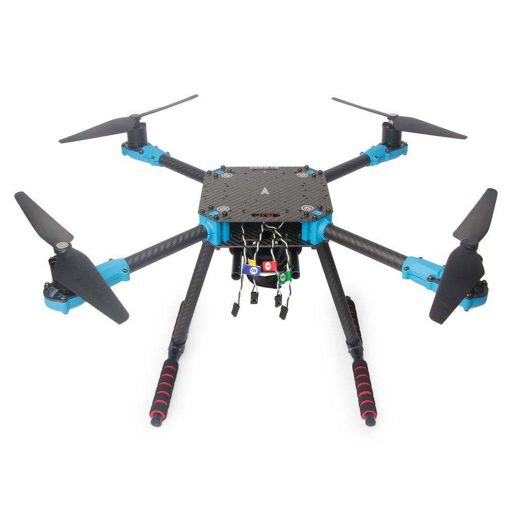
500 mm motor diagonal.
Photo: Holybro.
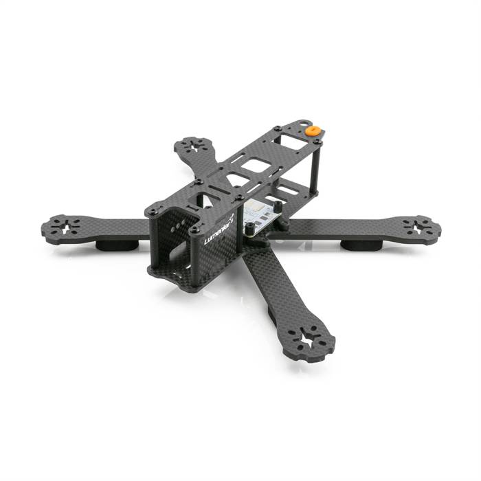
220 mm motor diagonal; 127 mm propellers.
Photo: Lumenier / GetFPV.
The photos identify the two frame sizes; they are not shown at the same scale.
The X500 illustrates a 500 mm platform. The baseline simulation’s 2.5644 kg
mass and aerodynamic parameters come from its existing gs_drone model;
they are not measured specifications for the pictured X500 kit.
The baseline FastDyn.Copter has a 500 mm motor diagonal (arm_length = 0.25)
and a 2.5644 kg mass. The small-frame example targets the original 5-inch
Lumenier QAV-R. Its specified motor diagonal is 220 mm, so the corresponding
center-to-motor arm length is 0.11 m. A 5-inch propeller has a 0.127 m
diameter. Lumenier’s QAV-R product specification
distinguishes this version from the 180 mm and 260 mm variants.
Changing only the arm length is insufficient. You also need to account for flying mass including battery, inertia, motor/propeller thrust, motor lag, aerodynamic drag, and ground-contact geometry. The frame’s wheelbase is a manufacturer dimension; inertia and propulsion depend on the actual build.
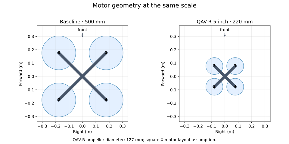
The layout diagram uses an idealized square-X arrangement. Its large-frame propeller diameter is 254 mm for illustration; the QAV-R propeller diameter is 127 mm. The original QAV-R’s specified diagonal is preserved, but detailed motor mounting coordinates still need a drawing or measurements for a specific build.
Read the smaller model
within FastDyn;

model Qavr "Original 5-inch QAV-R: 220 mm diagonal; assumed tutorial equipment"
  import Vehicles;
  import Geodesy;
  parameter Real bare_mass = 0.50 "Flying mass including battery [kg]";
  parameter Real bare_inertia[3,3] = diagonal({0.0008973333333333334, 0.00126, 0.002066666666666667})
    "Estimated inertia of the equipped frame [kg*m^2]";

  extends Copter(
    mass = bare_mass, inertia = bare_inertia,
    arm_length = 0.11,
    Ct = 1.6e-6, Cm = 0.009, omega_max = 2300,
    tau_up = 0.015, tau_down = 0.025,
    body_area = 0.01936,
    drag_area = {0.011616, 0.015488, 0.023232},
    linear_drag = {0.023232, 0.023232, 0.034848},
    leg_x = 0.07, leg_y = 0.07, leg_z = -0.03,
    ground_k = 600, ground_c = 30, ground_tangent_c = 5);
end Qavr;
The 0.50 kg equipped mass, inertia tensor, motor coefficients, drag, and motor
lag are explicit tutorial assumptions. The arm_length = 0.11 setting is half
the specified 220 mm motor diagonal. In the later payload study, this tensor
stays fixed while the prescribed payload weight changes.
Select this model with an overlay:
# Overlay for configs/copter462.toml. Vehicle defaults live in Modelica.
[FMU]
active = "qavr"

[FMU.models.qavr]
model = "FastDyn.Qavr"
model_file = "modelica/FastDyn/Qavr.mo"
source_roots = ["modelica", "third_party/common/modelica_models"]
output = "out/fmi3/Qavr"
build = true

[FMU.models.qavr.parameters]
lat0 = 40.414929
lon0 = -86.932387
ground_alt_wgs84 = 149.0
In your chosen environment, type:
fastdyn-config --base configs/copter462.toml \
  --overlay configs/models/qavr.toml --output out/qavr.toml
Expected output begins Created out/qavr.toml. Open that generated file and
check that [FMU].active is qavr and its class is FastDyn.Qavr.
Tune before the mission
Before flying a full mission with the smaller vehicle, compare controller responses in the emulated ArduCopter firmware. The existing ArduPilot Holybro QAV250 parameter set is a candidate gain seed from another small frame. It does not establish a validated QAV-R tune. Hardware-specific ESC, battery, and notch settings must not be copied without matching the modeled hardware.
Continue to the measured controller comparison. Inspect the recorded ±5° responses and the selected gains’ ±10° validation, then export those gains and use them for your QAV-R mission.
Experimental gain tuning
Changing the airframe changes the plant seen by the controller. The same controller torque command produces a different angular acceleration when the inertia changes. Motor response and available thrust also affect the useful gain range.
For the one-hour walkthrough, inspect the recorded comparison and apply the selected gains. You can run the tuning trials yourself using the commands below when you have more time.
1. Choose a documented starting point
The experiment compares the ArduCopter defaults with roll/pitch rate gains from the Copter 4.6.2 Holybro QAV250 parameter file. The QAV250 supplies a seed from another small frame. Use the measured responses below to decide whether that seed is suitable for this simulated QAV-R. The initial comparison keeps the angle-loop gains the same while varying rate gains and their filters.
Show all trial settings and candidate gains
# All trial settings and firmware parameters are versioned here.
[experiment]
connect = "udpin:127.0.0.1:14552"
altitude_m = 8.0
settle_s = 4.0
timeout_s = 180.0
monitor_port = 5565
startup_stream_rate_hz = 4
attitude_rate_hz = 50
minimum_attitude_rate_hz = 25
steps = [
  {duration_s=2.0, roll_deg=0.0, pitch_deg=0.0},
  {duration_s=2.0, roll_deg=5.0, pitch_deg=0.0},
  {duration_s=2.0, roll_deg=-5.0, pitch_deg=0.0},
  {duration_s=2.0, roll_deg=0.0, pitch_deg=0.0},
  {duration_s=2.0, roll_deg=0.0, pitch_deg=5.0},
  {duration_s=2.0, roll_deg=0.0, pitch_deg=-5.0},
  {duration_s=2.0, roll_deg=0.0, pitch_deg=0.0},
]

[parameters]
BRD_SAFETY_DEFLT = 0
FS_THR_ENABLE = 0
FS_GCS_ENABLE = 0
DISARM_DELAY = 0
EK3_SRC1_POSZ = 3
EK3_SRC2_POSZ = 3
EK3_SRC3_POSZ = 3
COMPASS_DEC = 0.0
COMPASS_AUTODEC = 0
ARMING_CHECK = 0
GUID_OPTIONS = 0
MOT_PWM_MIN = 1100
MOT_PWM_MAX = 1900
MOT_THST_EXPO = 0.5
MOT_THST_HOVER = 0.2

# ArduCopter 4.6.2 defaults, explicitly recorded for comparison.
[candidates.default]
ATC_RAT_RLL_P = 0.135
ATC_RAT_RLL_I = 0.135
ATC_RAT_RLL_D = 0.0036
ATC_RAT_PIT_P = 0.135
ATC_RAT_PIT_I = 0.135
ATC_RAT_PIT_D = 0.0036
ATC_ANG_RLL_P = 4.5
ATC_ANG_PIT_P = 4.5

# Rate gains/filter values from ArduPilot Copter-4.6.2 Holybro-QAV250.param.
# Keep the same outer-loop settings while comparing the rate controllers.
[candidates.qav250]
ATC_RAT_RLL_P = 0.04598495
ATC_RAT_RLL_I = 0.04598495
ATC_RAT_RLL_D = 0.00120043
ATC_RAT_PIT_P = 0.07421205
ATC_RAT_PIT_I = 0.07421205
ATC_RAT_PIT_D = 0.001949416
ATC_RAT_RLL_FLTT = 40.0
ATC_RAT_RLL_FLTD = 40.0
ATC_RAT_PIT_FLTT = 40.0
ATC_RAT_PIT_FLTD = 40.0
ATC_ANG_RLL_P = 4.5
ATC_ANG_PIT_P = 4.5
2. Run a controlled maneuver
The runner in utils/tune_copter.py creates a fresh run for each candidate,
confirms parameter values returned by the firmware, takes off in GUIDED mode,
and commands alternating roll and pitch steps. It records actual attitude,
controller target rates, altitude, and motor PWM, then lands.
After generating out/qavr.toml in the preceding chapter, type:
python utils/tune_copter.py --config configs/tuning/qavr.toml \
  --run-config out/qavr.toml --output out/tuning
For each successful run, look for
[tuning] attitude experiment completed and landed and the per-candidate
attitude.csv, mission.tlog, trial.toml, and console.log files, plus a
combined results.json.
The helper requests 50 Hz attitude telemetry; analysis refuses runs below 25 Hz. MAVProxy’s periodic stream-rate request is disabled for this experiment so it cannot overwrite the helper’s rates. Each recorded comparison contains 700 attitude samples over 14 seconds.
3. Decide from the response
Compare attitude error during transitions and after settling. RMSE is root-mean-square error; lower values mean closer tracking. Check rate tracking, sustained oscillation, altitude retention, and motor limits. Keep the chosen gains fixed while increasing the maneuver amplitude for a separate validation run, then fly the waypoint mission. Diagnose compiler or startup errors before drawing conclusions about the gains.
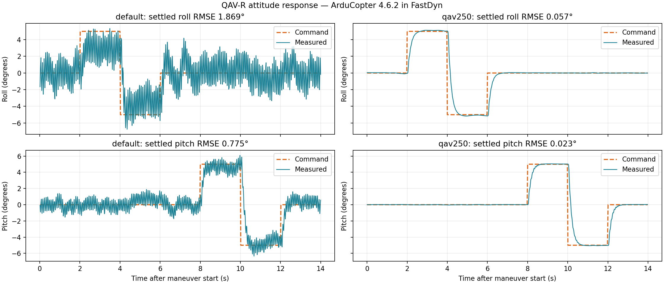
| Candidate | Settled roll RMSE | Settled pitch RMSE | Altitude during steps |
|---|---|---|---|
| ArduCopter defaults | 1.869° | 0.775° | 7.994–8.045 m |
| QAV250 seed | 0.057° | 0.023° | 7.994–8.042 m |
These measurements use the current array-based model and Rumoca 21843c11.
“Settled” includes samples more than one second after each command change.
Both candidates finished and landed, but the default gains produced sustained
oscillation. The selected QAV250 seed also passed an independent ±10°
experiment: settled roll/pitch RMSE was 0.070°/0.049°, and altitude remained
8.005–8.041 m. This is a tested choice for these maneuvers, not an optimal-gain claim.
Comparison results · Default CSV · Selected CSV · Selected MAVLink log · Validation results · Compiler and model provenance
Reproduce the larger maneuver and plot either batch:
python utils/tune_copter.py --config docs/book/assets/qavr-tuning/validation.toml \
  --candidate qav250 --run-config out/qavr.toml --output out/tuning-validation
python utils/tuning_report.py --input out/tuning --output out/tuning-response.png
4. Use the selected gains for a mission
Export the settings from the source TOML, then apply the controller overlay:
python utils/tune_copter.py --config configs/tuning/qavr.toml \
  --candidate qav250 --export-parameters out/qavr-controller.param
fastdyn-config --base configs/copter462.toml \
  --overlay configs/models/qavr.toml \
  --overlay configs/models/qavr-controller.toml --output out/qavr.toml
fastdyn run -c out/qavr.toml -o out/qavr/work
Expect Wrote out/qavr-controller.param (27 parameters), then mission progress
ending in final landing confirmed near ground. This waypoint mission passed
with the selected gains. Keep the controller overlay for the next physics
experiment so that a model change is the only intended difference.
The procedure follows the distinction between initial stabilization and later tuning in ArduPilot’s tuning process. These experiments tune the simulated plant; transferring gains to hardware requires its own validation.
Apply a load at the front-right motor
Use a 50 g payload mass to prescribe a 0.49 N downward force at the front-right motor (motor 1). In the assumed square-X layout, this is 77.8 mm forward and 77.8 mm right of the center, in the motor plane. The QAV-R’s mass and inertia stay at their original values. You will convert mass to weight, rotate the force into body coordinates, then compute its moment.
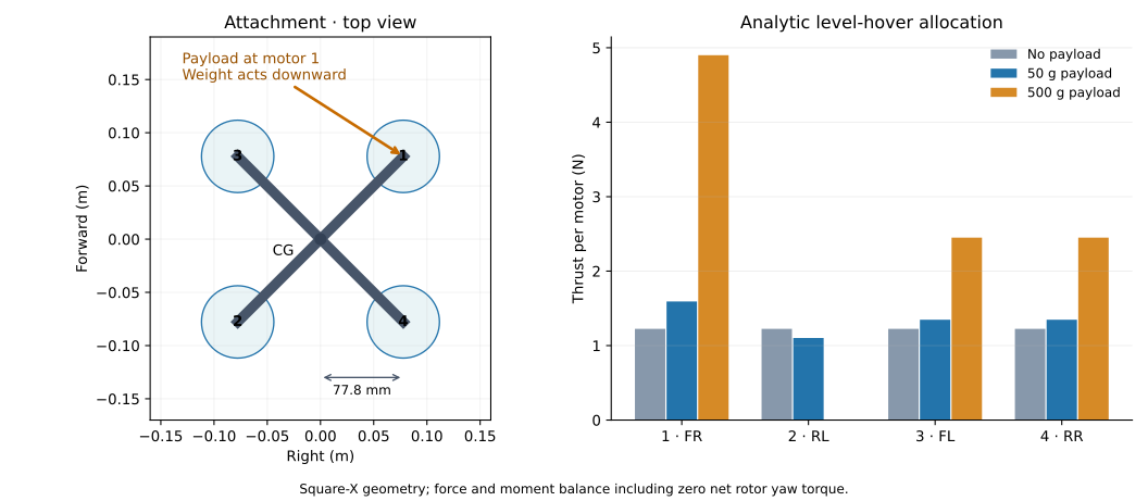
1. Read the complete load model
within FastDyn;

model QavrSidePayload "QAV-R with a downward load at its front-right motor"
  import Vehicles;
  import Geodesy;
  parameter Real payload_mass = 0.05
    "Payload mass used to prescribe its weight; payload inertia is omitted [kg]";
  // Independent coordinates stay writable as FMI parameters. These equal
  // {0.11 / sqrt(2), -0.11 / sqrt(2), 0} for the assumed QAV-R motor layout.
  parameter Real attachment_b[3] = {0.07778174593052023, -0.07778174593052023, 0}
    "Front-right motor (motor 1), from CG in body FLU [m]";

  extends Qavr(plant(external_force_b = force_b, external_moment_b = moment_b));

  Real force_world[3] "Prescribed payload weight in world NWU [N]";
  Real force_b[3] "Applied force expressed in body FLU [N]";
  Real moment_b[3] "Moment about vehicle CG in body FLU [N*m]";
equation
  // The load stays world-down when the aircraft tilts.
  force_world = {0, 0, -payload_mass * plant.gravity};
  force_b = transpose(plant.R) * force_world;
  moment_b = cross(attachment_b, force_b);
  // This is an external load, not an additional rigid body's inertial dynamics.
end QavrSidePayload;
force_world is expressed in world north, west, up, so its negative Z
component points down. attachment_b is expressed in body forward, left, up,
so negative Y puts the attachment on the right. plant.R rotates body vectors
to world coordinates; its transpose converts the world force into body axes.
The force therefore stays world-down when the vehicle tilts.
The applied weight is payload_mass * plant.gravity. Its moment follows the
familiar lever-arm relation:
[ M_b = r_b \times F_b. ]
With a level vehicle and the default 50 g payload mass:
force_b  = {0, 0, -0.49} N
moment_b = {0.038113, 0.038113, 0} N m
The moment is about the existing vehicle CG. Apply the force and moment once; there is no additional mass, CG shift, or inertia correction in this example.
2. See where the force enters the physics
The library template at the pinned revision sums its forces internally and
does not yet expose external-load inputs. FastDyn keeps a local adaptation,
modelica/FastDyn/QuadrotorWithExternalWrench.mo, of
Vehicles.Templates.QuadrotorPlant. It adds two body-frame inputs and adds them
to the force and moment sums before rigid-body integration:
  M_b = M_rotor + M_rate + M_ground_b + external_moment_b;
  F_b = F_ground_b + drag_b + {0, 0, T} + external_force_b;
The normal Copter and QAV-R models bind those inputs to zero. QavrSidePayload
binds them to the force and moment computed above. Motor response, drag, ground
contacts, and the rigid-body equations still come from the template design.
This changes plant physics while preserving FastDyn’s PWM and sensor interface.
Complete quadrotor template with external-load inputs
within FastDyn;

// Adapted from Vehicles.Templates.QuadrotorPlant in modelica_models
// dfdb3294f61ab639a8a8be19611a1f69187a3ff7 (Apache-2.0).
// The only physics changes are two body-frame load inputs added to F_b/M_b.
// Keep this local adaptation until the upstream template exposes load inputs.
// Parameterized 6-DOF quadrotor plant model.
//
// Inputs:  4 motor angular velocities [rad/s]
// States:  rigid body pose/velocity plus motor speeds
//
// Internal frame uses local world Z Up and body axes Forward-Left-Up.
//
// Motor layout (ArduPilot Quad-X output order):
//   1: front-right  CCW   2: rear-left   CCW
//   3: front-left   CW    4: rear-right  CW

model QuadrotorWithExternalWrench
  parameter Real vehicle_mass = 2.0 "Total vehicle mass [kg]";
  parameter Real gravity = 9.80665 "Gravitational acceleration [m/s2]";
  parameter Real vehicle_ixx = 0.02166666666666667 "Body inertia xx [kg*m^2]";
  parameter Real vehicle_iyy = 0.02166666666666667 "Body inertia yy [kg*m^2]";
  parameter Real vehicle_izz = 0.04000000000000001 "Body inertia zz [kg*m^2]";

  extends RigidBody.RigidBody6DOF(
    mass = vehicle_mass,
    g = gravity,
    ixx = vehicle_ixx,
    iyy = vehicle_iyy,
    izz = vehicle_izz,
    p_start = {0, 0, ground_z - leg_z + initial_ground_clearance},
    qnorm_gain = 1.0
  );

  // Aerodynamic and actuator parameters
  parameter Real Ct = 8.54858e-6 "Thrust coefficient [N/(rad/s)^2]";
  parameter Real Cm = 0.016 "Rotor torque/thrust ratio [m]";
  parameter Real arm_length = 0.25 "Arm length [m]";
  parameter Real d = arm_length / sqrt(2.0) "Effective moment arm [m]";
  parameter Real Cl_p = -0.2 "Rolling moment coefficient per roll rate";
  parameter Real Cm_q = -0.2 "Pitching moment coefficient per pitch rate";
  parameter Real Cn_r = -0.1 "Yawing moment coefficient per yaw rate";
  parameter Real motor_thrust_scale[4] = {1, 1, 1, 1}
    "Per-motor thrust effectiveness multiplier for fault/robustness studies";
  parameter Real S = 0.1 "Reference area [m^2]";
  parameter Real CdA[3] = {0.06, 0.08, 0.12} "Body-axis drag area [m^2]";
  parameter Real linear_drag[3] = {0.12, 0.12, 0.18} "Low-speed body-axis drag [N/(m/s)]";
  parameter Real rho = 1.225 "Air density [kg/m^3]";
  parameter Real mag_world_enu[3] = {0.0, 0.21, -0.45}
    "Magnetic field in world ENU axes [Gauss]";

  // Ground contact (spring-damper)
  parameter Real ground_k = 3000 "Ground stiffness per contact point [N/m]";
  parameter Real ground_c = 150 "Ground normal damping per contact point [N*s/m]";
  parameter Real ground_tangent_c = 25 "Ground tangential damping per contact point [N*s/m]";
  parameter Real ground_z = 0.0 "World Z coordinate of the ground collision plane [m]";
  parameter Real initial_ground_clearance = 0.02 "Initial landing-leg clearance above the ground plane [m]";
  parameter Real leg_x = 0.17 "Landing contact X offset from CG [m]";
  parameter Real leg_y = 0.17 "Landing contact Y offset from CG [m]";
  parameter Real leg_z = -0.10 "Landing contact Z offset from CG [m]";

  // Motor first-order response
  parameter Real tau_up = 0.0125 "Motor spin-up time constant [s]";
  parameter Real tau_down = 0.025 "Motor spin-down time constant [s]";
  parameter Real motor_tau_eps = 1.0 "Smooth transition width for asymmetric motor lag [rad/s]";
  parameter Real motor_moment_map[3, 4] = [
    -d,   d,   d,  -d;
    -d,   d,  -d,   d;
   -Cm, -Cm,  Cm,  Cm
  ] "Motor thrust to body moment map";
  parameter Real rate_damping[3] = {
    4 * S * arm_length * Cl_p,
    4 * S * arm_length * Cm_q,
    4 * S * arm_length * Cn_r
  } "Body rate damping coefficients";

  model Motor
    parameter Real Ct = 8.54858e-6 "Thrust coefficient [N/(rad/s)^2]";
    parameter Real tau_up = 0.0125 "Motor spin-up time constant [s]";
    parameter Real tau_down = 0.025 "Motor spin-down time constant [s]";
    parameter Real tau_inv_mid = 0.5 * (1.0 / tau_up + 1.0 / tau_down) "Mean inverse motor lag [1/s]";
    parameter Real tau_inv_delta = 0.5 * (1.0 / tau_up - 1.0 / tau_down) "Signed inverse motor lag half-range [1/s]";
    parameter Real tau_eps = 1.0 "Smooth transition width for asymmetric lag [rad/s]";

    input Real omega_cmd(start = 0) "Commanded speed [rad/s]";
    output Real omega(start = 0, fixed = true) "Actual speed [rad/s]";
    output Real thrust "Motor thrust [N]";

  protected
    Real omega_error "Motor speed tracking error [rad/s]";
    Real lag_blend "Smooth lag blend";
    Real tau_inv "Smooth inverse lag [1/s]";

  equation
    omega_error = omega_cmd - omega;
    lag_blend = omega_error / sqrt(omega_error * omega_error + tau_eps * tau_eps);
    tau_inv = tau_inv_mid + tau_inv_delta * lag_blend;
    der(omega) = tau_inv * omega_error;
    thrust = Ct * omega * omega;
  end Motor;

  input Real external_force_b[3](start = {0, 0, 0}) "Applied body FLU force [N]";
  input Real external_moment_b[3](start = {0, 0, 0}) "Applied body FLU moment about CG [N*m]";

  input Real omega_cmd[4](start = {0, 0, 0, 0}) "Motor commands [rad/s]";

  output Real position[3](start = p_start) "World position [m]";
  output Real velocity[3](start = v_b_start) "World velocity [m/s]";
  output Real quat[4](start = q_start) "Quaternion w,x,y,z";
  output Real omega_m[4](start = {0, 0, 0, 0}) "Motor actual speeds [rad/s]";
  output Real accel[3](start = {0, 0, 0})
    "Body FLU accelerometer [m/s^2] (specific force)";
  output Real gyro[3](start = {0, 0, 0}) "Body FLU gyroscope [rad/s]";
  output Real mag[3](start = {0, 0.21, -0.45})
    "Body FLU magnetometer [Gauss]";

protected
  Motor motor[4](each Ct = Ct, each tau_up = tau_up, each tau_down = tau_down, each tau_eps = motor_tau_eps);
  Real F_m[4] "Motor thrusts [N]";
  Real T "Total motor thrust [N]";
  Real M_rotor[3] "Rotor moment in body FLU [N*m]";
  Real M_rate[3] "Rate damping moment in body FLU [N*m]";
  Real V "Airspeed magnitude [m/s]";
  Real drag_b[3] "Body drag force [N]";
  Real leg_h_w[4] "Landing contact world Z positions [m]";
  parameter Real leg_r_b[3, 4] = [
    leg_x, -leg_x, leg_x, -leg_x;
    -leg_y, leg_y, leg_y, -leg_y;
    leg_z, leg_z, leg_z, leg_z
  ] "Landing contact offsets in body FLU [m]";
  Real leg_v_b[3, 4] "Landing contact velocities in body [m/s]";
  Real leg_f_w[3, 4] "Landing contact forces in world [N]";
  Real leg_f_b[3, 4] "Landing contact forces in body [N]";
  Real leg_m_b[3, 4] "Landing contact moments in body [N*m]";
  Real F_ground_b[3] "Total ground force in body FLU [N]";
  Real M_ground_b[3] "Total ground moment in body FLU [N*m]";

equation
  motor.omega_cmd = omega_cmd;
  omega_m = motor.omega;
  F_m = motor.thrust .* motor_thrust_scale;
  T = F_m[1] + F_m[2] + F_m[3] + F_m[4];

  V = sqrt(v_b[1] * v_b[1] + v_b[2] * v_b[2] + v_b[3] * v_b[3] + 1e-12);
  drag_b = -0.5 * rho * V * (CdA .* v_b) - linear_drag .* v_b;

  M_rotor = motor_moment_map * F_m;
  M_rate = rate_damping .* omega;

  for i in 1:4 loop
    leg_v_b[:, i] = v_b + cross(omega, leg_r_b[:, i]);
    leg_h_w[i] = p[3] + R[3, :] * leg_r_b[:, i];
    leg_f_w[1, i] = if noEvent(leg_h_w[i] < ground_z) then
      -ground_tangent_c * (R[1, :] * leg_v_b[:, i]) else 0;
    leg_f_w[2, i] = if noEvent(leg_h_w[i] < ground_z) then
      -ground_tangent_c * (R[2, :] * leg_v_b[:, i]) else 0;
    leg_f_w[3, i] = if noEvent(leg_h_w[i] < ground_z) then
      noEvent(max(0, ground_k * (ground_z - leg_h_w[i]) -
        ground_c * (R[3, :] * leg_v_b[:, i]))) else 0;
    leg_m_b[:, i] = cross(leg_r_b[:, i], leg_f_b[:, i]);
  end for;

  leg_f_b = transpose(R) * leg_f_w;

  F_ground_b = leg_f_b * {1, 1, 1, 1};
  M_ground_b = leg_m_b * {1, 1, 1, 1};

  // ANCHOR: applied-wrench
  M_b = M_rotor + M_rate + M_ground_b + external_moment_b;
  F_b = F_ground_b + drag_b + {0, 0, T} + external_force_b;
  // ANCHOR_END: applied-wrench

  accel = a_b;
  gyro = omega;
  mag = transpose(R) * mag_world_enu;

  position = p;
  velocity = v_w;
  quat = q;

end QuadrotorWithExternalWrench;
3. Choose the load in TOML
# Overlay for configs/copter462.toml: external force at a body attachment point.
[FMU]
active = "qavr_payload"

[FMU.models.qavr_payload]
model = "FastDyn.QavrSidePayload"
model_file = "modelica/FastDyn/QavrSidePayload.mo"
source_roots = ["modelica", "third_party/common/modelica_models"]
output = "out/fmi3/QavrSidePayload"
build = true

[FMU.models.qavr_payload.parameters]
payload_mass = 0.05 # kg; applies a 0.49 N downward load at 9.8 m/s²
attachment_b = [0.07778174593052023, -0.07778174593052023, 0.0] # front-right motor
In your chosen environment, generate the configuration:
fastdyn-config --base configs/copter462.toml \
  --overlay configs/models/qavr-side-payload.toml \
  --overlay configs/models/qavr-controller.toml --output out/payload.toml
Expected output begins Created out/payload.toml. The selected class is
FastDyn.QavrSidePayload. Set payload_mass = 0.0 for no load or
payload_mass = 0.10 for a 100 g payload’s weight. Change attachment_b to
move the attachment point. Keep these choices in the overlay TOML.
The controller overlay uses out/qavr-controller.param, exported in the
gain-tuning chapter.
The attachment coordinates are independent parameters so FMI can accept the
TOML override; if you change the frame geometry, update the attachment too.
4. Predict, then check the response
At level hover, total rotor thrust must rise from 4.90 N to 5.39 N. The front-right load creates both roll and pitch moments. Balancing those moments and the rotor yaw torques predicts the following thrusts for the 50 g example:
| Motor | Position | Predicted thrust |
|---|---|---|
| 1 | Front-right, at the payload | 1.593 N |
| 2 | Rear-left, diagonally opposite | 1.103 N |
| 3 | Front-left | 1.348 N |
| 4 | Rear-right | 1.348 N |
The diagonally opposite motor reduces thrust while the other motors increase it. These are analytic level-hover predictions, not measured mission results. The next chapter derives the allocation and compares missions with larger loads.
Use your unloaded QAV-R mission as the baseline. Check the roll and pitch moment directions above, then run the same mission with the constant load and fixed controller gains:
fastdyn run -c out/payload.toml -o out/payload/work
The recorded run completed its waypoints and landed with the same selected controller as the unloaded QAV-R. Explore its measured trajectory and altitude:
Static constant-load trajectory and altitude plot
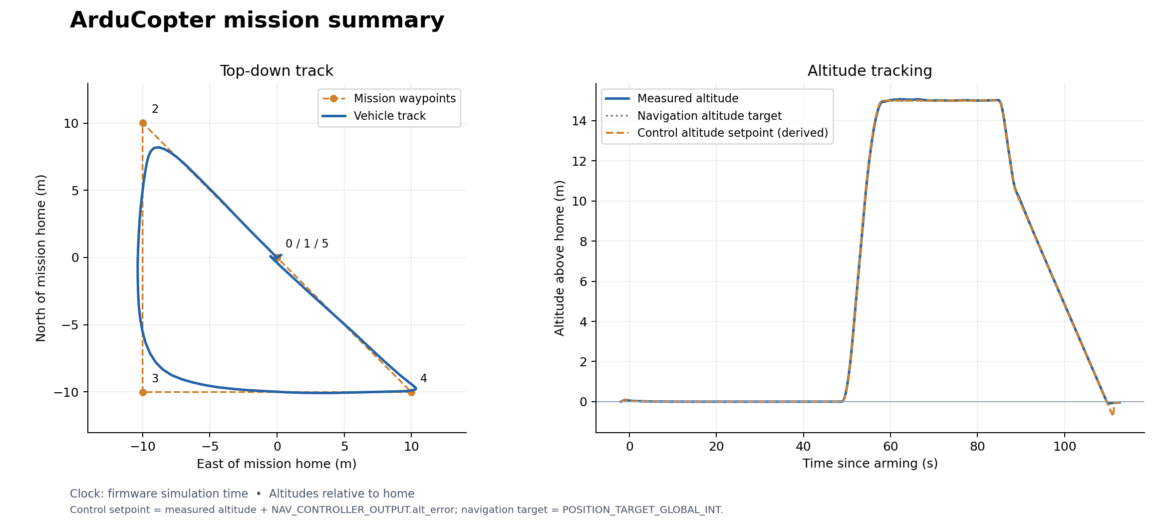
Telemetry · Console log · CSV · Run provenance
5. Change an equation, rebuild, and fly
Now model a smoothly varying downward tension, instead of constant weight. This changes the force law while retaining the same motor geometry, firmware, controller, and sensor interface. Create your own source file:
cp modelica/FastDyn/QavrSidePayload.mo modelica/FastDyn/MyLoad.mo
Open modelica/FastDyn/MyLoad.mo in your editor. Rename the opening
model QavrSidePayload and closing end QavrSidePayload; to MyLoad. Before
the equation section, add:
parameter Real modulation = 0.5 "Fractional change about mean tension";
parameter Real period = 5.0 "Tension period [s]";
Replace the constant force_world equation with:
force_world = {0, 0, -payload_mass * plant.gravity *
  (1 + modulation * sin(2 * pi * time / period))};
Keep period > 0 and 0 <= modulation <= 1. At the defaults, the downward
force varies from 0.245 N to 0.735 N, with a mean of 0.49 N. It should be
largest at 1.25 s and smallest at 3.75 s. time is simulation time, not wall
time; the applied tension also varies before takeoff.
Save this complete overlay as out/my-load.toml:
[FMU]
active = "my_load"

[FMU.models.my_load]
model = "FastDyn.MyLoad"
model_file = "modelica/FastDyn/MyLoad.mo"
source_roots = ["modelica", "third_party/common/modelica_models"]
output = "out/fmi3/MyLoad"
build = true

[FMU.models.my_load.parameters]
payload_mass = 0.05
modulation = 0.5
period = 5.0
Build and check the actual force before flying:
fastdyn-config --base configs/copter462.toml --overlay out/my-load.toml \
  --overlay configs/models/qavr-controller.toml --output out/my-load-run.toml
python utils/build_fmi3_fmu.py --config out/my-load-run.toml --skip-submodules
python tests/integration/payload_model_test.py out/fmi3/MyLoad/FastDyn_MyLoad.fmu
fastdyn run -c out/my-load-run.toml -o out/my-load-run/work
Expect an FMU named FastDyn_MyLoad.fmu, force checks of 0.735, 0.490,
0.245, and 0.490 N at 1.25, 2.5, 3.75, and 5 s, and a mission ending with
final landing confirmed near ground. The native check also verifies that
the vehicle’s inertial mass remains 0.5 kg and the moment is r × F.
The complete reference implementation is FastDyn.QavrVaryingLoad below.
Its recorded mission uses the same new equation and selected gains:
Complete varying-tension model
within FastDyn;

model QavrVaryingLoad "QAV-R with a smoothly varying tension at the front-right motor"
  import Vehicles;
  import Geodesy;
  parameter Real payload_mass = 0.05 "Reference mass for the mean applied weight [kg]";
  parameter Real modulation = 0.5 "Fractional variation about the mean, between 0 and 1";
  parameter Real period = 5.0 "Load period [s], greater than zero";
  // Independent coordinates, matching 0.11 / sqrt(2) at the QAV-R motor.
  parameter Real attachment_b[3] = {0.07778174593052023, -0.07778174593052023, 0}
    "Front-right motor, from CG in body FLU [m]";

  extends Qavr(plant(external_force_b = force_b, external_moment_b = moment_b));

  Real force_world[3] "Prescribed tension in world NWU [N]";
  Real force_b[3] "Applied force in body FLU [N]";
  Real moment_b[3] "Moment about the vehicle CG in body FLU [N*m]";
equation
  assert(period > 0 and modulation >= 0 and modulation <= 1,
    "Use a positive period and modulation between zero and one");
  // Compared with QavrSidePayload, the force law now varies continuously in time.
  force_world = {0, 0, -payload_mass * plant.gravity *
    (1 + modulation * sin(2 * pi * time / period))};
  force_b = transpose(plant.R) * force_world;
  moment_b = cross(attachment_b, force_b);
end QavrVaryingLoad;
Static varying-load trajectory and altitude plot
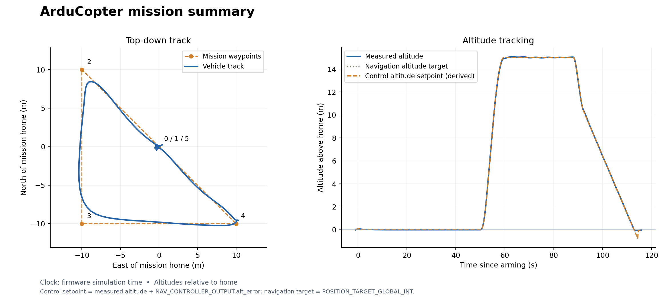
Telemetry · Console log · CSV · Run provenance
Compare the two altitude traces and waypoint paths, then change the modulation or period in your overlay and repeat. The native force check verifies the compiled equation at its default parameters, even when the controller rejects much of the disturbance in flight. Keep both run logs; a similar-looking trajectory does not mean the plant stayed the same. This is the edit → compile → check → run → compare workflow to reuse for your own physics.
What this approximation represents
This model exactly describes a prescribed external force at a body attachment point, such as an idealized tension load. Its 0.49 N downward force also equals the weight of 50 g under the model’s 9.8 m/s² gravity, so it approximates that payload’s static hover load.
A real attached payload also resists linear and angular acceleration. A freely hanging payload can swing and change the applied tension. Those effects require additional payload dynamics or changes to the combined mass properties. Keep this exercise focused on an external disturbance; do not use it to claim accurate payload motion during aggressive maneuvers. Next, the payload Monte Carlo study varies this same payload mass while holding the attachment point, vehicle properties, and controller fixed.
Payload Monte Carlo study
Continue the load-at-a-motor experiment: how much prescribed
payload weight can the fixed controller tolerate on the same waypoint mission?
Vary the payload mass used in F = m g, keeping its attachment at the
front-right motor, 77.8 mm forward and 77.8 mm right of the center, in the
motor plane. The QAV-R’s own mass, inertia,
geometry, motors, firmware, gains, and mission stay fixed.
The recorded batch contains 18 runs: nine completed missions (including the unloaded reference) and nine firmware crash disarms. The heaviest successful sample was 321.6 g; the lightest failed sample was 359.8 g. These are observations for this mission and controller, not an exact stability boundary. The plant models ground contact at landing points; motion after tipping is not a detailed airframe collision reconstruction.
Start with the recorded trajectories below. For a short hands-on check, run the zero-load reference in step 4. The complete batch is an optional longer experiment; you can replot its archived logs immediately using step 6.
1. Inspect the recorded flights
Every recorded trajectory is shown on common axes. The zero-load reference is dark, completed missions are blue, and flights stopped by a failure criterion are red. Select a mass to highlight that run; the other paths remain visible. Crosses mark the final sample of interrupted runs. Runs without position telemetry remain in the table.
Static plot of all trajectories and altitude traces
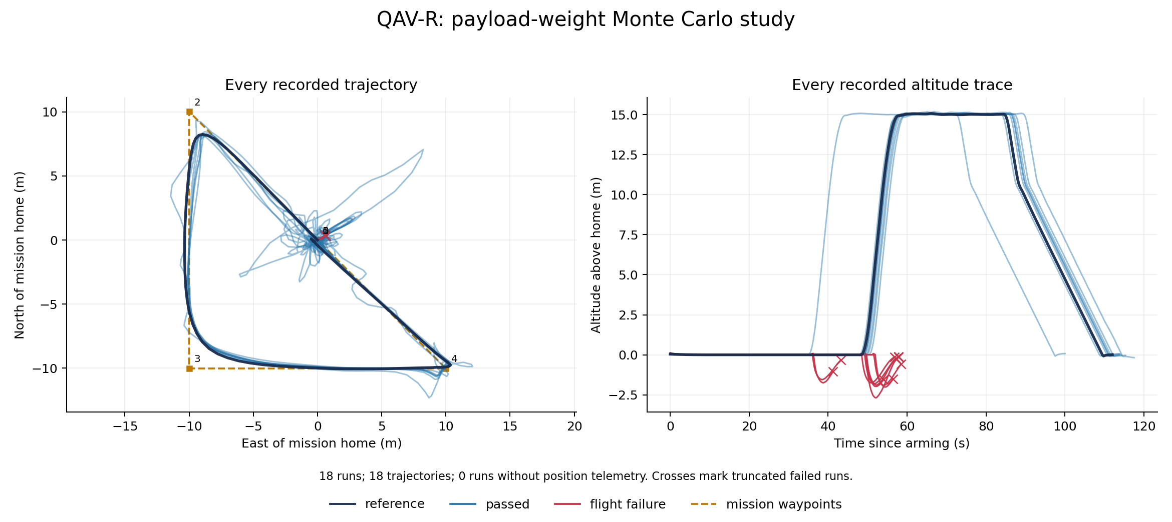
18 of 18 runs completed (including the nominal reference).
| Run | Payload mass (g) | Result | Peak armed tilt |
|---|---|---|---|
| reference | 0.0 | reference | 16.9° |
| payload-limit | 500.0 | flight failure | 179.2° |
| run-000 | 438.7 | flight failure | 179.0° |
| run-001 | 220.6 | passed | 27.5° |
| run-002 | 198.4 | passed | 23.4° |
| run-003 | 488.3 | flight failure | 178.8° |
| run-004 | 70.0 | passed | 15.3° |
| run-005 | 231.2 | passed | 28.9° |
| run-006 | 359.8 | flight failure | 179.5° |
| run-007 | 430.6 | flight failure | 179.2° |
| run-008 | 430.0 | flight failure | 178.6° |
| run-009 | 321.6 | passed | 40.9° |
| run-010 | 472.2 | flight failure | 179.1° |
| run-011 | 485.5 | flight failure | 178.9° |
| run-012 | 242.2 | passed | 28.8° |
| run-013 | 226.6 | passed | 28.6° |
| run-014 | 225.3 | passed | 27.3° |
| run-015 | 391.5 | flight failure | 179.0° |
Peak armed tilt includes takeoff and ground contact. The separate sustained-tilt stop criterion activates only after the vehicle has risen above 2 m. The firmware’s own crash check can disarm it before that height.
Download SVG · All trajectory data · Run manifest · Study settings and controller gains · Model library license
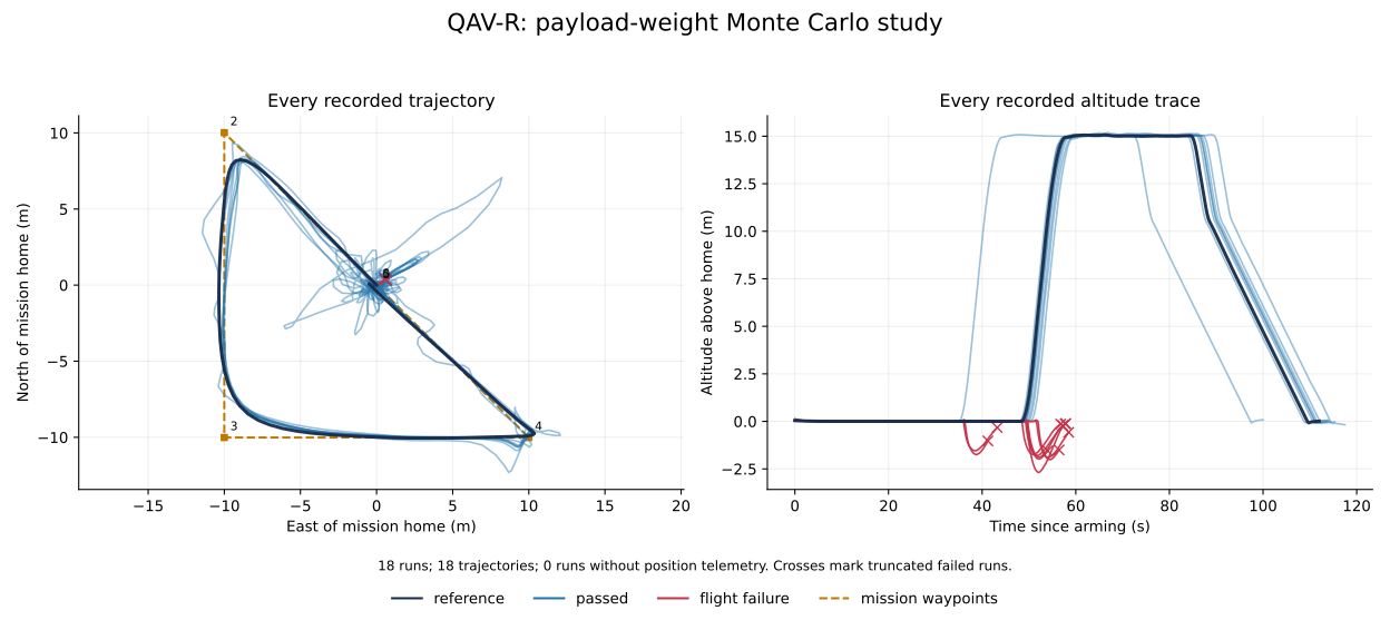
Which model produced these results?
Each trial extends the same FastDyn.QavrSidePayload model from the preceding
chapter and uses the environment’s pinned Rumoca compiler. The QAV-R geometry,
array-valued inertia, motor response, and selected controller gains stay fixed.
Only the prescribed payload mass changes. The run manifest records source and
compiler provenance alongside the measured results.
Generated zero-load QAV-R variant
within FastDyn;
model PayloadTrial
  import Vehicles;
  import Geodesy;
  import RigidBody;
  extends QavrSidePayload(
    bare_mass=0.5,
    payload_mass=0,
    attachment_b={0.07778174593052023, -0.07778174593052023, 0});
end PayloadTrial;
2. Understand the sampled quantity
The primary model exposes the scalar payload_mass in kilograms:
within FastDyn;

model QavrSidePayload "QAV-R with a downward load at its front-right motor"
  import Vehicles;
  import Geodesy;
  parameter Real payload_mass = 0.05
    "Payload mass used to prescribe its weight; payload inertia is omitted [kg]";
  // Independent coordinates stay writable as FMI parameters. These equal
  // {0.11 / sqrt(2), -0.11 / sqrt(2), 0} for the assumed QAV-R motor layout.
  parameter Real attachment_b[3] = {0.07778174593052023, -0.07778174593052023, 0}
    "Front-right motor (motor 1), from CG in body FLU [m]";

  extends Qavr(plant(external_force_b = force_b, external_moment_b = moment_b));

  Real force_world[3] "Prescribed payload weight in world NWU [N]";
  Real force_b[3] "Applied force expressed in body FLU [N]";
  Real moment_b[3] "Moment about vehicle CG in body FLU [N*m]";
equation
  // The load stays world-down when the aircraft tilts.
  force_world = {0, 0, -payload_mass * plant.gravity};
  force_b = transpose(plant.R) * force_world;
  moment_b = cross(attachment_b, force_b);
  // This is an external load, not an additional rigid body's inertial dynamics.
end QavrSidePayload;
At level attitude, a 50 g mass gives a downward force of 0.49 N and a positive body-FLU roll moment and pitch moment of approximately 0.0381 N m each. A 100 g mass doubles both. The force remains world-down as the aircraft tilts. Each trial compiles its own FMU so the load also reaches any derived expressions evaluated during compilation.
This study uses a zero-load reference, 16 uniformly sampled masses from
0 to 500 g, and an explicit 500 g upper-limit run. NumPy’s PCG64 generator
uses seed 462. The upper limit is 100% of the original 500 g vehicle
weight: payload_mass / vehicle_mass <= 1.0. At this endpoint the combined
static weight is equivalent to 1.0 kg under gravity. The uniform distribution
explores the selected range; it does not estimate how frequently real payload
masses occur.
This is the external-load approximation from the preceding chapter: changing
payload_mass changes the prescribed weight, not the vehicle’s inertial
mass. It does not simulate the payload’s swinging or acceleration-dependent
tension. Those require additional dynamics.
3. Predict the trend before running
More payload weight requires more total thrust and more unequal motor effort.
Let W = 0.50 * 9.8 be the original vehicle weight and P = payload_mass * 9.8
be the applied load. Balancing total thrust, roll, pitch, and yaw at level hover
for this square-X motor layout gives:
T1 (front-right, payload motor) = (W + 3 P) / 4
T2 (rear-left, opposite motor)  = (W - P) / 4
T3 (front-left) = T4 (rear-right) = (W + P) / 4
At 500 g of payload, the force is 4.90 N, with 0.381 N m of roll moment and the same pitch moment. The ideal allocation is 4.90 N, 0 N, 2.45 N, 2.45 N for motors 1–4. Motor 2 reaches zero thrust, leaving no room to reduce it further. This motivates testing the endpoint: transients and the fixed controller may lose control before or near that condition.
4. Run the experiment
Use your chosen environment:
fastdyn-config --base configs/copter462.toml \
  --overlay configs/models/qavr-side-payload.toml --output out/payload-base.toml
python utils/payload_study.py --config configs/monte-carlo/payload.toml \
  --run-config out/payload-base.toml --limit 1
The reference run should report:
[study] reference: payload 0.0 g
[study] reference: reference — Final mission item and landing confirmed
Remove --limit 1 to run the full batch. The runner resumes completed samples
in the same output directory and refuses to mix changed experiment inputs.
Choose a fresh output directory when changing the study or controller. Run one
batch at a time because the configured MAVLink ports are shared.
The runner snapshots the current model sources and generates each trial’s Modelica class. Edit the study TOML to change sweep settings; the runner replaces generated trial sources. Develop a different force law in a separately maintained model and validate it before automating its trials.
All persistent settings, including controller parameters, are in TOML:
# Payload range: 0 to 100% of the ORIGINAL vehicle mass (0 to 500 g).
# Attachment: motor 1, front-right, in body FLU.
# Same array-based model and selected gains as the load exercise.
[study]
title = "QAV-R: payload-weight Monte Carlo study"
seed = 462
samples = 16
distribution = "uniform"
attachment_b_m = [
    0.07778174593052023,
    -0.07778174593052023,
    0.0,
]
modelica_models_revision = "dfdb3294f61ab639a8a8be19611a1f69187a3ff7"
rumoca_revision = "21843c115cd4b4c7fa02011d18a6c1e501ebb387"
rumoca_version = "0.10.0"
mission = "virtuals/physics/flight_controllers/courbet/mavlink/copter_mission.waypoints"
vehicle_mass_kg = 0.5
max_payload_to_vehicle_mass_ratio = 1.0

[execution]
output = "out/payload-experiment"
# Optional: set to docs/book/assets/payload-study after reviewing a full batch.
publish = ""
wall_timeout_s = 150
monitor_port = 5565
max_tilt_deg = 60.0
tilt_duration_s = 1.0
max_altitude_m = 50.0

[parameters]
BRD_SAFETY_DEFLT = 0
FS_THR_ENABLE = 0
FS_GCS_ENABLE = 0
DISARM_DELAY = 0
EK3_SRC1_POSZ = 3
EK3_SRC2_POSZ = 3
EK3_SRC3_POSZ = 3
COMPASS_DEC = 0.0
COMPASS_AUTODEC = 0
ARMING_CHECK = 0
GUID_OPTIONS = 0
MOT_PWM_MIN = 1100
MOT_PWM_MAX = 1900
MOT_THST_EXPO = 0.5
MOT_THST_HOVER = 0.2
ATC_RAT_RLL_P = 0.04598495
ATC_RAT_RLL_I = 0.04598495
ATC_RAT_RLL_D = 0.00120043
ATC_RAT_PIT_P = 0.07421205
ATC_RAT_PIT_I = 0.07421205
ATC_RAT_PIT_D = 0.001949416
ATC_RAT_RLL_FLTT = 40.0
ATC_RAT_RLL_FLTD = 40.0
ATC_RAT_PIT_FLTT = 40.0
ATC_RAT_PIT_FLTD = 40.0
ATC_ANG_RLL_P = 4.5
ATC_ANG_PIT_P = 4.5
Expect a Modelica variant, compiled FMU, controller parameter file, run TOML,
console log, MAVLink log, and result.json for each trial. The publish
setting is optional and is empty by default, so your one-run check
does not replace the book’s archived results. Find the new figures under
out/payload-experiment/report/. To publish a reviewed full batch into this
book, set publish = "docs/book/assets/payload-study" before starting a fresh
output directory.
5. Interpret the outcomes
Every run starts fresh firmware and separate RAM files, then loads the same controller parameters. Completing the Copter mission requires the final item and landing confirmation. FastDyn and its separate helper processes are stopped before the next trial starts.
The experiment stops a flight if sampled tilt exceeds 60° across at least
1 s after becoming airborne, altitude exceeds 50 m, or the firmware
reports crash disarming. Tilt is acos(cos(roll) * cos(pitch)); this uses the
recorded MAVLink samples and does not certify behavior between samples.
A flight that arms but misses the completion deadline is mission incomplete. A compiler or startup failure is a run error. These labels distinguish an observed flight failure from an unavailable simulation; a timeout alone does not establish instability. Partial failed-run trajectories are retained.
A finite Monte Carlo sample can reveal failures at particular masses. It cannot prove an exact stability boundary or establish that every unsampled mass will work. To refine a transition, narrow the mass interval in TOML, use a new output directory, and repeat with the same controller.
6. Replot the archived logs
In your chosen environment, regenerate the plot from the book’s saved measurements:
python utils/monte_carlo_report.py \
  --config docs/book/assets/payload-study/runs.toml \
  --output out/payload-replot
The command reports the total number of runs, available trajectories, and runs without position telemetry. Both interactive and static figures include every available path, including interrupted flights.
Mission logs, plots, and models
Explore recorded ArduCopter, ArduPlane, and ArduRover missions below. Drag a time slider, click the lower plot, or press Replay. Each panel has its own controls. The gray track shows the complete route, the blue trace advances with time, and the red marker shows the selected sample. Numbered points are the uploaded mission waypoints.
The Copter and Rover recordings use this checkout’s pinned compiler and array-based models. Their downloadable summaries record source revisions and model hashes. Plane is a historical recording: the current three-wheel model is included in the repository, but its FMI export awaits compiler event support.
| Vehicle | Completion check | Model status |
|---|---|---|
| ArduCopter | Final mission item, low altitude, and firmware ON_GROUND | Current model, rerun successfully |
| ArduRover | Final waypoint 4 reached | Current model, rerun successfully |
| ArduPlane | Waypoint 11 reached while airborne | Historical recording; current model not flight-validated |
The console logs confirm completion independently of the trajectory plot.
ArduCopter
The 500 mm quadrotor takes off, visits its waypoints, and lands. Compare measured altitude with the derived controller setpoint using the checkbox.
Static Copter trajectory and altitude figure
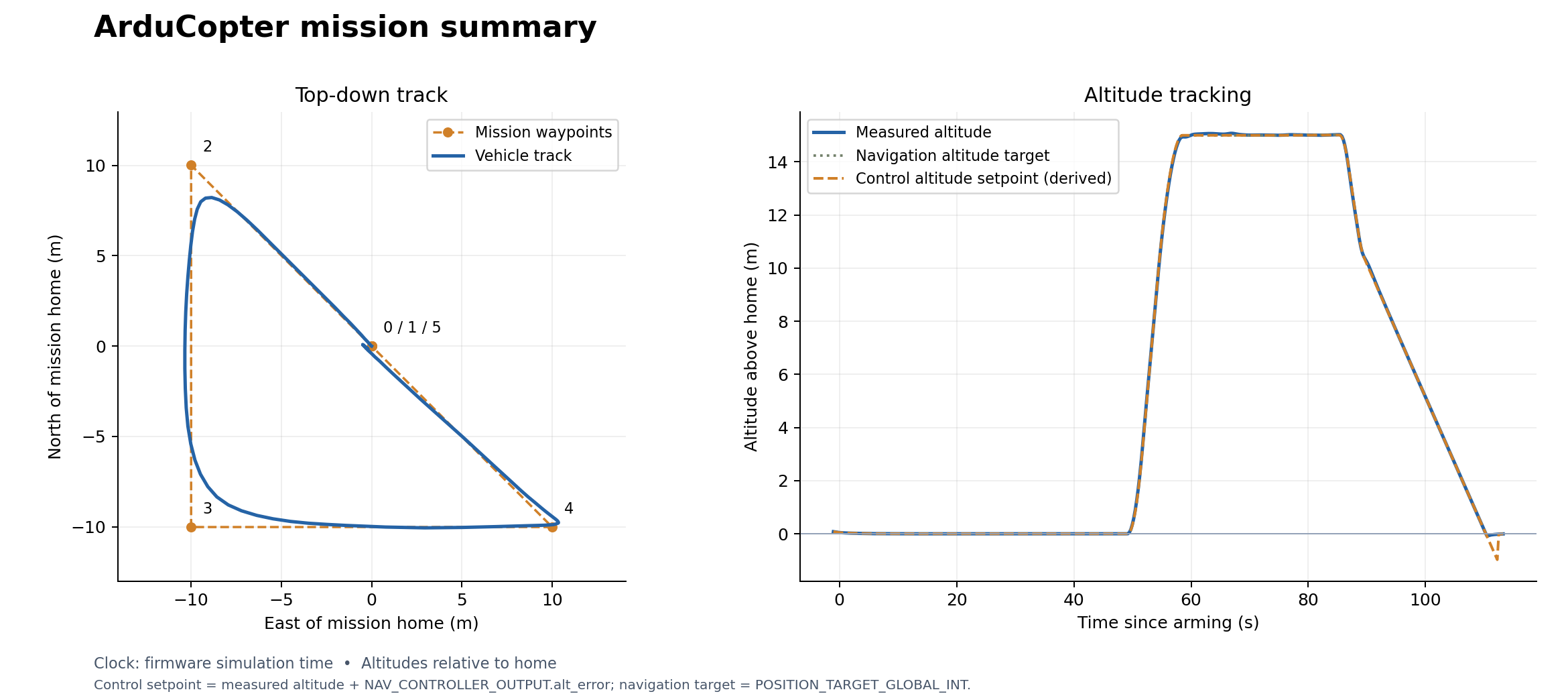
SVG · CSV · MAVLink log · Console log · Mission file · Run summary
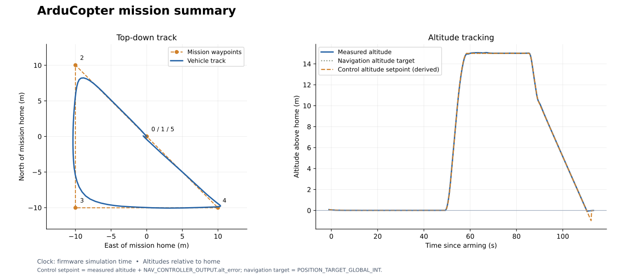
Model used for this run: FastDyn.Copter
within FastDyn;

model Copter
  parameter Real mass = 2.5644001 "Gazebo gs_drone equivalent mass [kg]";
  parameter Real inertia[3,3] = diagonal({0.02601237985, 0.02590943825, 0.045571756801})
    "Inertia about the CG in body FLU [kg*m^2]";
  parameter Real Ct = 8.54858e-6 "Thrust coefficient [N/(rad/s)^2]";
  parameter Real Cm = 0.016 "Rotor torque/thrust ratio [m]";
  parameter Real arm_length = 0.25 "Arm length [m]";
  parameter Real Cl_p = -0.2 "Rolling moment coefficient per roll rate";
  parameter Real Cm_q = -0.2 "Pitching moment coefficient per pitch rate";
  parameter Real Cn_r = -0.1 "Yawing moment coefficient per yaw rate";
  parameter Real tau_up = 0.0125 "Motor spin-up time constant [s]";
  parameter Real tau_down = 0.025 "Motor spin-down time constant [s]";
  parameter Real body_area = 0.1 "Reference area for rate damping [m^2]";
  parameter Real drag_area[3] = {0.06, 0.08, 0.12} "Body drag areas [m^2]";
  parameter Real linear_drag[3] = {0.12, 0.12, 0.18} "Body linear drag [N*s/m]";
  parameter Real leg_x = 0.17 "Ground contact X offset [m]";
  parameter Real leg_y = 0.17 "Ground contact Y offset [m]";
  parameter Real leg_z = -0.10 "Ground contact Z offset in body FLU [m]";
  parameter Real ground_k = 3000 "Contact stiffness [N/m]";
  parameter Real ground_c = 150 "Contact normal damping [N*s/m]";
  parameter Real ground_tangent_c = 25 "Contact tangential damping [N*s/m]";

  FastDyn.QuadrotorWithExternalWrench plant(
    external_force_b = {0, 0, 0},
    external_moment_b = {0, 0, 0},
    ground_z = 0.0,
    vehicle_mass = mass,
    J = inertia,
    gravity = 9.8,
    mag_world_enu = {0.21, 0, -0.45},
    Ct = Ct,
    Cm = Cm,
    arm_length = arm_length,
    Cl_p = Cl_p,
    Cm_q = Cm_q,
    Cn_r = Cn_r,
    tau_up = tau_up,
    tau_down = tau_down,
    S = body_area,
    CdA = drag_area,
    linear_drag = linear_drag,
    leg_x = leg_x,
    leg_y = leg_y,
    leg_z = leg_z,
    ground_k = ground_k,
    ground_c = ground_c,
    ground_tangent_c = ground_tangent_c);

  parameter Real pwm_min = 1100.0 "Minimum motor PWM used by the Gazebo gs_drone ArduPilot control block";
  parameter Real pwm_max = 1900.0 "Maximum motor PWM used by the Gazebo gs_drone ArduPilot control block";
  parameter Real omega_min = 0.0 "Motor speed at minimum PWM [rad/s]";
  parameter Real omega_max = 1300.0 "Aerodynamic motor speed at maximum PWM [rad/s]";
  parameter Real lat0 = 40.414929 "Reference latitude [deg]";
  parameter Real lon0 = -86.932387 "Reference longitude [deg]";
  parameter Real ground_alt_wgs84 = 149.0 "WGS84 ellipsoid altitude of the local ground collision plane [m]";
  parameter Real accel_bias[3] = {0, 0, 0} "Accelerometer bias [m/s^2]";
  parameter Real gyro_bias[3] = {0, 0, 0} "Gyroscope bias [rad/s]";
  parameter Real mag_bias[3] = {0, 0, 0} "Magnetometer bias [Gauss]";
  parameter Real gps_bias[3] = {0, 0, 0} "GPS bias N/E/altitude [m]";
  parameter Real baro_alt_bias = 0.0 "Barometer relative altitude bias [m]";
  parameter Real earth_radius_m = 6378137.0 "Spherical Earth radius used for local geodetic conversion [m]";
  parameter Real pi = 3.141592653589793;

  input Real pwm[4](start = {1000, 1000, 1000, 1000}) "Motor PWM commands";

  output Real accel[3] "Body FRD accelerometer [m/s^2]";
  output Real gyro[3] "Body FRD gyroscope [rad/s]";
  output Real mag[3] "Body FRD magnetometer [Gauss]";
  output Real gps[3] "GPS latitude, longitude, altitude";
  output Real vel_ned[3] "GPS velocity NED [m/s]";
  output Real yaw_deg "Yaw [deg]";
  output Real baro_altitude_m "Barometer relative altitude [m]";
  output Real baro_pressure_pa "Barometer pressure [Pa]";
  output Real baro_temperature_c "Barometer temperature [degC]";
  output Real baro_climb_rate_mps "Barometer climb rate [m/s]";
  output Real motor_cmd[4] "Motor commands after PWM scaling [rad/s]";

protected
  Real pwm_span;
  Real pwm_norm[4];
  Real gps_lat_lon[2];
  Real geodetic_origin[3] "Reference latitude, longitude, and Earth radius";
  Real yaw_rad;

equation
  pwm_span = pwm_max - pwm_min;

  for i in 1:4 loop
    pwm_norm[i] = min(1.0, max(0.0, (pwm[i] - pwm_min) / pwm_span));
    motor_cmd[i] = omega_min + (omega_max - omega_min) * pwm_norm[i];
    plant.omega_cmd[i] = motor_cmd[i];
  end for;

  accel = {plant.accel[1], -plant.accel[2], -plant.accel[3]} + accel_bias;
  gyro = {plant.gyro[1], -plant.gyro[2], -plant.gyro[3]} + gyro_bias;
  mag = {plant.mag[1], -plant.mag[2], -plant.mag[3]} + mag_bias;

  // Avoid collisions between the caller parameters and the function locals
  // during function projection in the pinned Rumoca compiler.
  geodetic_origin = {lat0, lon0, earth_radius_m};
  gps_lat_lon = Geodesy.localNorthEastToLatLon(
    geodetic_origin[1],
    geodetic_origin[2],
    plant.p[1] + gps_bias[1],
    -plant.p[2] + gps_bias[2],
    geodetic_origin[3]);
  gps[1] = gps_lat_lon[1];
  gps[2] = gps_lat_lon[2];
  gps[3] = ground_alt_wgs84 + plant.p[3] + gps_bias[3];

  vel_ned[1] = plant.v_w[1];
  vel_ned[2] = -plant.v_w[2];
  vel_ned[3] = -plant.v_w[3];

  yaw_rad = atan2(2.0 * (plant.q[1] * plant.q[4] + plant.q[2] * plant.q[3]),
                  1.0 - 2.0 * (plant.q[3] * plant.q[3] + plant.q[4] * plant.q[4]));
  yaw_deg = -yaw_rad * 180.0 / pi;

  baro_altitude_m = plant.p[3] + baro_alt_bias;
  baro_temperature_c = 15.0 - 0.0065 * (ground_alt_wgs84 + baro_altitude_m);
  baro_pressure_pa = 101325.0 * (1.0 - 2.25577e-5 * (ground_alt_wgs84 + baro_altitude_m)) ^ 5.25588;
  baro_climb_rate_mps = plant.v_w[3];
end Copter;
The wrapper maps four PWM commands to motor speeds and connects
Vehicles.Templates.QuadrotorPlant to FastDyn’s sensor interface. See the
model walkthrough for its array parameters and equations.
fastdyn-config --base configs/copter462.toml --output out/copter.toml
fastdyn run -c out/copter.toml -o out/copter/work
ArduPlane
Historical result: the fixed-wing aircraft starts stationary, takes off to 100 m, and flies a waypoint circuit. This run ends after waypoint 11 is reached while the plane is still airborne. It demonstrates takeoff and navigation; automatic landing has not been tested by this mission.
Static Plane trajectory and altitude figure
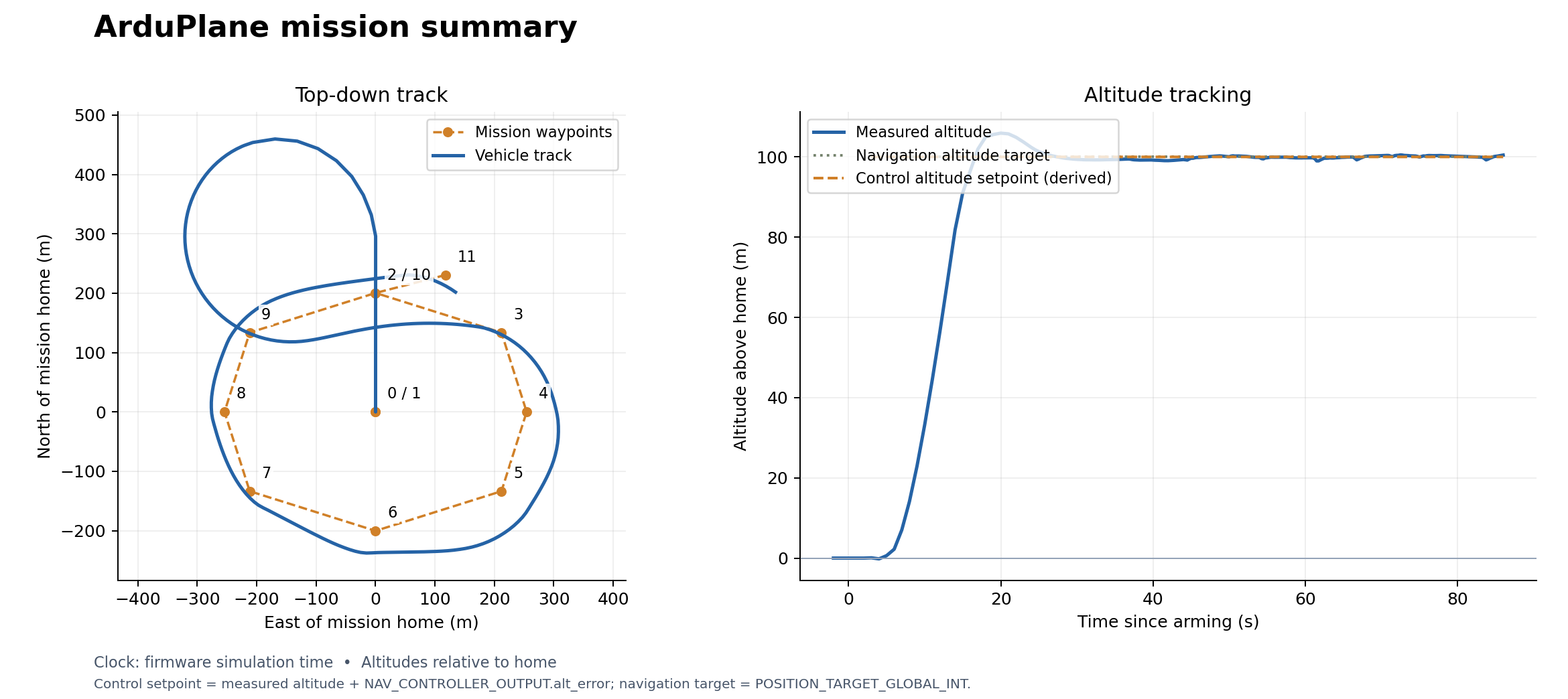
SVG · CSV · MAVLink log · Console log · Mission file · Run summary
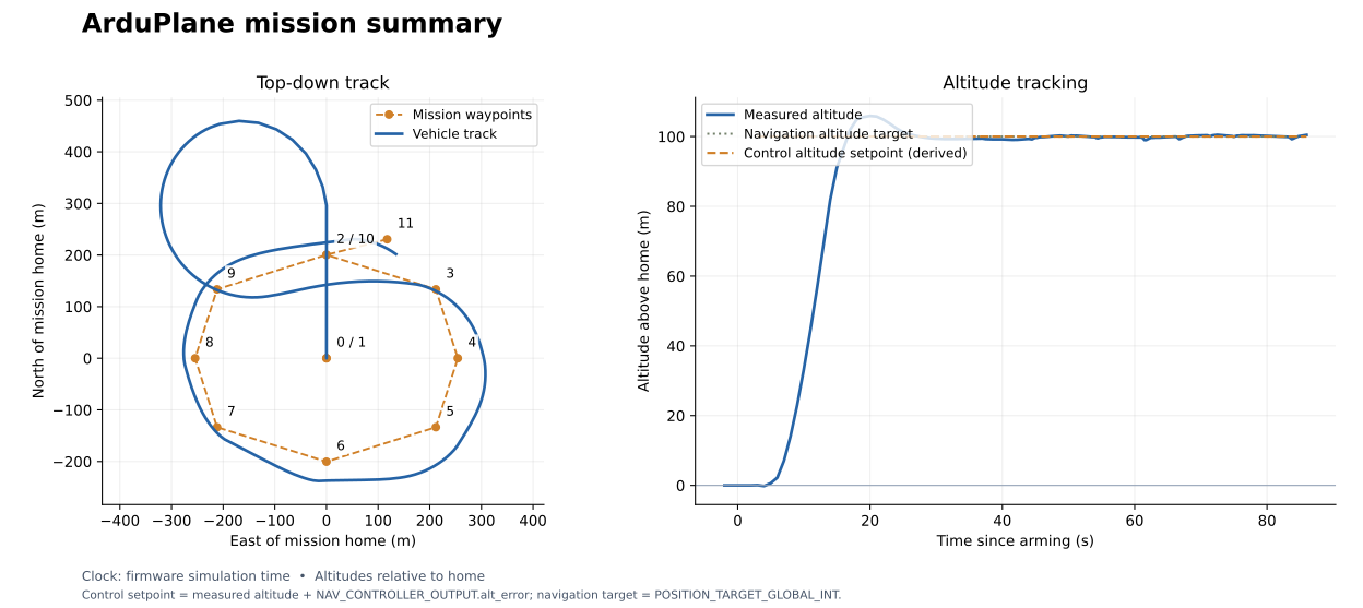
Model used for this run: FastDyn.Plane
within FastDyn;

model Plane
  // Start stationary on the ground while the firmware initializes its sensors.
  RigidBody.Examples.FixedWingPlant plant(
    p_start = {0, 0, 0}, v_b_start = {0, 0, 0},
    // The plant defines alpha from FLU vertical velocity, so nose-up flight
    // has negative alpha. Lift must increase as that angle becomes negative.
    CL_alpha = -4.2);

  parameter Real pwm_min = 1000.0 "Minimum PWM";
  parameter Real pwm_trim = 1500.0 "Neutral PWM";
  parameter Real pwm_max = 2000.0 "Maximum PWM";
  parameter Real Cn_beta = 0.10 "Yaw stability coefficient per FLU sideslip [1/rad]";
  parameter Real lat0 = 40.414929 "Reference latitude [deg]";
  parameter Real lon0 = -86.932387 "Reference longitude [deg]";
  parameter Real ground_alt_wgs84 = 149.0 "WGS84 ellipsoid altitude of the local ground plane [m]";
  parameter Real accel_bias[3] = {0, 0, 0} "Accelerometer bias [m/s^2]";
  parameter Real gyro_bias[3] = {0, 0, 0} "Gyroscope bias [rad/s]";
  parameter Real mag_bias[3] = {0, 0, 0} "Magnetometer bias [Gauss]";
  parameter Real gps_bias[3] = {0, 0, 0} "GPS bias N/E/altitude [m]";
  parameter Real baro_alt_bias = 0.0 "Barometer relative altitude bias [m]";
  parameter Real earth_radius_m = 6378137.0 "Spherical Earth radius used for local geodetic conversion [m]";
  parameter Real pi = 3.141592653589793;

  input Real pwm[4](start = {1500, 1500, 1000, 1500}) "Servo PWM commands";

  output Real accel[3] "Body FRD accelerometer [m/s^2]";
  output Real gyro[3] "Body FRD gyroscope [rad/s]";
  output Real mag[3] "Body FRD magnetometer [Gauss]";
  output Real gps[3] "GPS latitude, longitude, altitude";
  output Real vel_ned[3] "GPS velocity NED [m/s]";
  output Real yaw_deg "Yaw [deg]";
  output Real baro_altitude_m "Barometer relative altitude [m]";
  output Real baro_pressure_pa "Barometer pressure [Pa]";
  output Real baro_temperature_c "Barometer temperature [degC]";
  output Real baro_climb_rate_mps "Barometer climb rate [m/s]";
  output Real motor_cmd[4] "Normalized aileron/elevator/throttle/rudder commands";

protected
  Real aileron;
  Real elevator;
  Real throttle;
  Real rudder;
  Real gps_lat_lon[2];
  Real geodetic_origin[3] "Reference latitude, longitude, and Earth radius";
  Real yaw_rad;

equation
  aileron = min(1.0, max(-1.0, (pwm[1] - pwm_trim) / (pwm_max - pwm_trim)));
  elevator = min(1.0, max(-1.0, (pwm[2] - pwm_trim) / (pwm_max - pwm_trim)));
  throttle = min(1.0, max(0.0, (pwm[3] - pwm_min) / (pwm_max - pwm_min)));
  rudder = min(1.0, max(-1.0, (pwm[4] - pwm_trim) / (pwm_max - pwm_trim)));

  plant.aileron = aileron;
  plant.elevator = elevator;
  plant.throttle = throttle;
  // The upstream plant has no vertical-tail sideslip moment. Include that
  // moment through its rudder term so a banked aircraft turns into its
  // velocity vector instead of settling into a constant-heading sideslip.
  plant.rudder = rudder + Cn_beta / plant.Cn_rudder * atan2(
    plant.v_b[2], sqrt(plant.v_b[1] ^ 2 + plant.v_b[3] ^ 2 + 0.01));

  accel = plant.accel + accel_bias;
  gyro = plant.gyro + gyro_bias;
  mag = plant.mag + mag_bias;

  // Avoid collisions between the caller parameters and the function locals
  // during function projection in the pinned Rumoca compiler.
  geodetic_origin = {lat0, lon0, earth_radius_m};
  gps_lat_lon = Geodesy.localNorthEastToLatLon(
    geodetic_origin[1],
    geodetic_origin[2],
    plant.p[1] + gps_bias[1],
    -plant.p[2] + gps_bias[2],
    geodetic_origin[3]);
  gps[1] = gps_lat_lon[1];
  gps[2] = gps_lat_lon[2];
  gps[3] = ground_alt_wgs84 + plant.p[3] + gps_bias[3];

  vel_ned[1] = plant.v_w[1];
  vel_ned[2] = -plant.v_w[2];
  vel_ned[3] = -plant.v_w[3];

  yaw_rad = atan2(2.0 * (plant.q[1] * plant.q[4] + plant.q[2] * plant.q[3]),
                  1.0 - 2.0 * (plant.q[3] * plant.q[3] + plant.q[4] * plant.q[4]));
  yaw_deg = -yaw_rad * 180.0 / pi;

  baro_altitude_m = plant.p[3] + baro_alt_bias;
  baro_temperature_c = 15.0 - 0.0065 * (ground_alt_wgs84 + baro_altitude_m);
  baro_pressure_pa = 101325.0 * (1.0 - 2.25577e-5 * (ground_alt_wgs84 + baro_altitude_m)) ^ 5.25588;
  baro_climb_rate_mps = plant.v_w[3];
  motor_cmd = {aileron, elevator, throttle, rudder};
end Plane;
The archived wrapper uses an earlier plant with a single ground contact. Its exact source and revision are preserved in the downloads above; it does not represent the new three-wheel landing gear.
The current Plane model and configuration instantiate
Vehicles.Templates.FixedWingPlant with two main wheels and a tailwheel.
The pinned compiler lowers this model but rejects FMI export of its contact
events. CI checks that boundary explicitly. Wait for event support and a new
flight validation before using this model for an ArduPlane exercise.
ArduRover
The rover follows four waypoints around a rectangle. The lower plot shows
ground speed, derived from the horizontal GPS velocity, because Rover
has no altitude controller. This recording’s home-altitude reference
was zero while its GPS altitude was near 149 m; its relative_alt field must
not be interpreted as the rover hovering 149 m above the ground.
Static Rover trajectory and speed figure
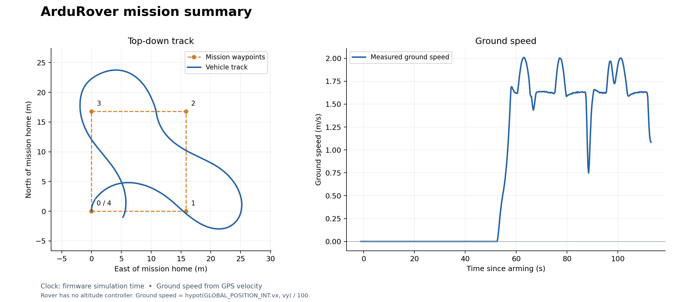
SVG · CSV · MAVLink log · Console log · Mission file · Run summary
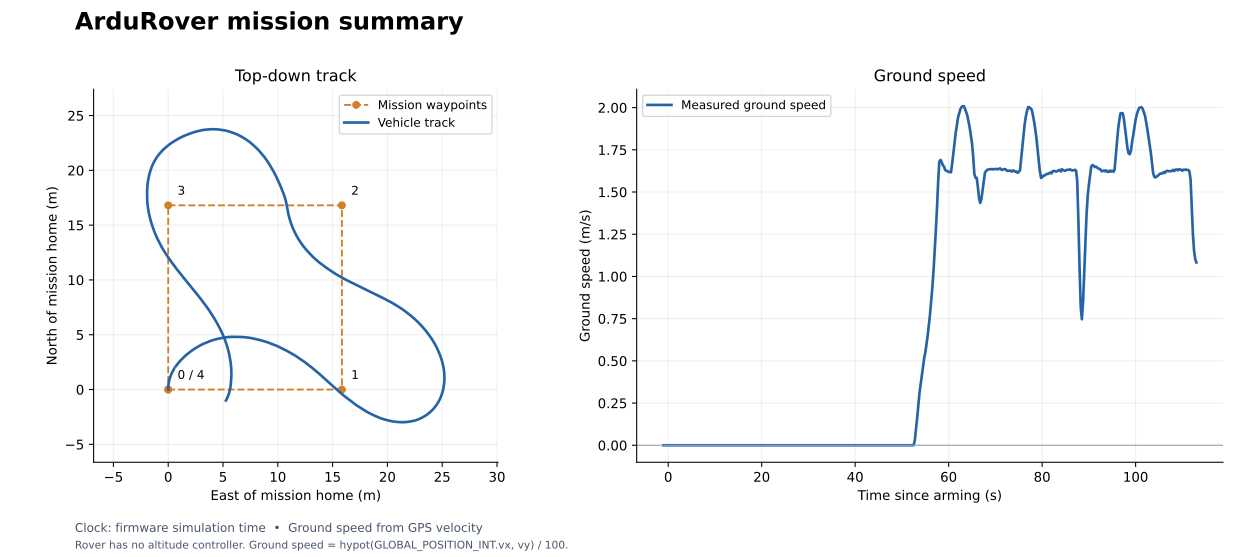
Model used for this run: FastDyn.Rover
within FastDyn;

model Rover
  RigidBody.Examples.RoverPlant plant(mag_world_enu = {0.21, 0, -0.45});

  parameter Real pwm_min = 1000.0 "Minimum PWM";
  parameter Real pwm_trim = 1500.0 "Neutral PWM";
  parameter Real pwm_max = 2000.0 "Maximum PWM";
  parameter Real lat0 = 40.414929 "Reference latitude [deg]";
  parameter Real lon0 = -86.932387 "Reference longitude [deg]";
  parameter Real ground_alt_wgs84 = 149.0 "WGS84 ellipsoid altitude of the local ground plane [m]";
  parameter Real accel_bias[3] = {0, 0, 0} "Accelerometer bias [m/s^2]";
  parameter Real gyro_bias[3] = {0, 0, 0} "Gyroscope bias [rad/s]";
  parameter Real mag_bias[3] = {0, 0, 0} "Magnetometer bias [Gauss]";
  parameter Real gps_bias[3] = {0, 0, 0} "GPS bias N/E/altitude [m]";
  parameter Real baro_alt_bias = 0.0 "Barometer relative altitude bias [m]";
  parameter Real earth_radius_m = 6378137.0 "Spherical Earth radius used for local geodetic conversion [m]";
  parameter Real pi = 3.141592653589793;

  input Real pwm[4](start = {1500, 1500, 1500, 1500}) "Servo PWM commands";

  output Real accel[3] "Body FRD accelerometer [m/s^2]";
  output Real gyro[3] "Body FRD gyroscope [rad/s]";
  output Real mag[3] "Body FRD magnetometer [Gauss]";
  output Real gps[3] "GPS latitude, longitude, altitude";
  output Real vel_ned[3] "GPS velocity NED [m/s]";
  output Real yaw_deg "Yaw [deg]";
  output Real baro_altitude_m "Barometer relative altitude [m]";
  output Real baro_pressure_pa "Barometer pressure [Pa]";
  output Real baro_temperature_c "Barometer temperature [degC]";
  output Real baro_climb_rate_mps "Barometer climb rate [m/s]";
  output Real motor_cmd[4] "Normalized steering/throttle commands";

protected
  Real steering;
  Real throttle;
  Real gps_lat_lon[2];
  Real geodetic_origin[3] "Reference latitude, longitude, and Earth radius";
  Real yaw_rad;

equation
  steering = min(1.0, max(-1.0, (pwm[1] - pwm_trim) / (pwm_max - pwm_trim)));
  throttle = min(1.0, max(-1.0, (pwm[3] - pwm_trim) / (pwm_max - pwm_trim)));
  plant.steering = steering;
  plant.throttle = throttle;

  accel = {plant.accel[1], -plant.accel[2], -plant.accel[3]} + accel_bias;
  gyro = {plant.gyro[1], -plant.gyro[2], -plant.gyro[3]} + gyro_bias;
  mag = {plant.mag[1], -plant.mag[2], -plant.mag[3]} + mag_bias;

  // Avoid collisions between the caller parameters and the function locals
  // during function projection in the pinned Rumoca compiler.
  geodetic_origin = {lat0, lon0, earth_radius_m};
  gps_lat_lon = Geodesy.localNorthEastToLatLon(
    geodetic_origin[1],
    geodetic_origin[2],
    plant.p[1] + gps_bias[1],
    -plant.p[2] + gps_bias[2],
    geodetic_origin[3]);
  gps[1] = gps_lat_lon[1];
  gps[2] = gps_lat_lon[2];
  gps[3] = ground_alt_wgs84 + plant.p[3] + gps_bias[3];

  vel_ned[1] = plant.v_w[1];
  vel_ned[2] = -plant.v_w[2];
  vel_ned[3] = -plant.v_w[3];

  yaw_rad = atan2(2.0 * (plant.q[1] * plant.q[4] + plant.q[2] * plant.q[3]),
                  1.0 - 2.0 * (plant.q[3] * plant.q[3] + plant.q[4] * plant.q[4]));
  yaw_deg = -yaw_rad * 180.0 / pi;

  baro_altitude_m = plant.p[3] + baro_alt_bias;
  baro_temperature_c = 15.0 - 0.0065 * (ground_alt_wgs84 + baro_altitude_m);
  baro_pressure_pa = 101325.0 * (1.0 - 2.25577e-5 * (ground_alt_wgs84 + baro_altitude_m)) ^ 5.25588;
  baro_climb_rate_mps = plant.v_w[3];
  motor_cmd = {steering, throttle, plant.v_b[1], plant.omega[3]};
end Rover;
Steering comes from PWM channel 1 and signed throttle from channel 3. The
wrapper connects them to Vehicles.Templates.RoverPlant and exposes the same
sensor interface to the firmware. See the complete Rover TOML.
fastdyn-config --base configs/rover462.toml --output out/rover.toml
fastdyn run -c out/rover.toml -o out/rover/work
Run the vehicle examples one at a time; their default ports are shared.
Rebuild the reports from these recordings
The book includes the original telemetry and uploaded waypoint files, so you can regenerate the figures without rerunning a simulation. In your chosen environment, from the repository root:
python -m fastdyn.mission_report --vehicle copter \
  --log docs/book/assets/baseline-mission.tlog \
  --mission docs/book/assets/baseline-mission.waypoints \
  --output out/reports/copter.png --require-setpoint

python -m fastdyn.mission_report --vehicle plane \
  --log docs/book/assets/plane-mission.tlog \
  --mission docs/book/assets/plane-mission.waypoints \
  --output out/reports/plane.png --require-setpoint

python -m fastdyn.mission_report --vehicle rover \
  --log docs/book/assets/rover-mission.tlog \
  --mission docs/book/assets/rover-mission.waypoints \
  --output out/reports/rover.png
Each command prints a JSON summary and writes PNG, SVG, CSV, and JSON files
under out/reports/. Plane and Rover finish at mission items 11 and 4. Copter can reset its mission cursor after landing; use the console completion marker and on-ground telemetry as the success check.
--require-setpoint checks that controller altitude telemetry was recorded;
it is used for Copter and Plane.
For these Copter and fixed-wing Plane runs, the derived altitude setpoint is
GLOBAL_POSITION_INT.relative_alt / 1000 + NAV_CONTROLLER_OUTPUT.alt_error.
Position and controller messages are paired by firmware time, so the estimate
can show small timing errors. POSITION_TARGET_GLOBAL_INT, when present,
provides a separate navigation target; the static plots include it after
conversion from absolute altitude using home altitude. It can differ from the
controller’s intermediate target during takeoff or climb. Rover sends zero for
alt_error; the report does not turn that placeholder into an altitude setpoint.
Record your own run
fastdyn-config configures MAVProxy to write out/<vehicle>/mission.tlog beside
the generated TOML’s other run files. Capture console output as well:
fastdyn run -c out/copter.toml -o out/copter/work > out/copter/console.log 2>&1
Use your new .tlog and the waypoint file actually uploaded to the vehicle as
the report inputs. Select --vehicle plane, --vehicle rover, or --vehicle copter
to get the correct title and plotted quantity.
CI runs complete Copter and Rover missions and reports the pending Plane export support separately. Download mission-report from a successful CI run for the telemetry, console logs, and summary plots. ci-logs contains additional build and runtime diagnostics.
Run models from the command line
Select the ArduCopter version
The Copter rehosting hooks are version-specific. Select the firmware and its matching hook/config set together with the version runner:
nix develop
python utils/run_copter_version.py --list
python utils/run_copter_version.py --version 4.7.0
python utils/run_copter_version.py --version 4.6.2
4.7 and 4.6 are accepted when they identify exactly one manifest entry.
Before rendering the configuration, the runner verifies the firmware and board
ROMFS-defaults SHA-256 values recorded in configs/copter_versions.toml; this
prevents a firmware binary from being combined accidentally with hooks or
defaults for another release. Use
--prepare-only to render and verify without starting QEMU, and --overlay
to add a normal FastDyn configuration overlay.
Choose an environment, then generate a config for the firmware and plant you want:
| Vehicle | Base config | Model | Mission completion |
|---|---|---|---|
| Copter 4.7.0 | configs/copter470.toml | FastDyn.Copter | Control loop, heartbeat, and GPS verified; EKF mission readiness pending |
| Copter 4.6.2 | configs/copter462.toml | FastDyn.Copter | Final landing |
| Rover | configs/rover462.toml | FastDyn.Rover | Final waypoint reached |
For Rover:
fastdyn-config --base configs/rover462.toml --output out/rover.toml
fastdyn run -c out/rover.toml -o out/rover/work
Run examples one at a time: their default MAVLink, viewer, and monitor ports are shared. Plane’s wrapper uses the library’s three-wheel fixed-wing template, but its contact events cannot yet be exported by the pinned compiler. Its configuration and source are included for inspection; use Copter or Rover for a runnable firmware simulation.
Build an FMU without starting firmware
Use the same TOML for compilation and execution:
python utils/build_fmi3_fmu.py --config out/copter.toml --skip-submodules
The first mission’s Copter writes out/fmi3/Copter/FastDyn_Copter.fmu.
--no-build generates source and metadata without compiling a shared library.
The current Rumoca also emits a portable source FMU; FastDyn normally compiles
its native library on first use and caches it beside the archive.
To compile the current array-based model directly:
rumoca compile modelica/FastDyn/Copter.mo \
  --model FastDyn.Copter \
  --source-root modelica \
  --source-root third_party/common/modelica_models \
  --output out/manual/Copter --target fmi3
The direct command compiles the Modelica defaults. FastDyn applies the numeric parameter overrides in TOML when it initializes the FMU.
Choose another model
Add another [FMU.models.<name>] entry with its model, model_file,
source_roots, and a distinct output directory. Set [FMU].active to that
name, or override the selection for one run:
fastdyn run -c out/copter.toml --fmu small_quad -o out/small_quad/work
That command requires an entry named small_quad in your TOML. A compatible
plant must expose FastDyn’s PWM and sensor interface. Copy the wrapper in
modelica/FastDyn/Copter.mo for a new quadrotor plant, preserving its output
names, dimensions, units, and body FRD/NED conventions. An arbitrary Modelica
model does not automatically implement that interface.
Run options
| Option | Purpose |
|---|---|
-c, --config PATH | Required TOML file |
-o, --work-dir PATH | Generated firmware/plugin configuration and run output |
--fmu NAME | Select a named FMU entry for this run |
--no-build-fmu | Use an existing artifact without automatic compilation |
--no-run-processes | Launch QEMU without configured MAVProxy or mission helpers |
-p, --persist-work-dir | Retain the existing generated work directory |
-m, --map-file PATH | Supply a symbol map |
-s, --svd PATH | Supply peripheral descriptions |
Use fastdyn run --help and python utils/build_fmi3_fmu.py --help for the
complete command-line help. Keep persistent model settings in TOML; CLI
overrides are useful for individual runs.
TOML configuration
Keep reusable settings in source TOML overlays and generate a complete TOML
for each run. The generated file records the firmware, tools, model, parameters,
and helper commands. The generator resolves tool locations and replaces legacy
${NAME:-default} expressions with their literal defaults.
For reusable changes, write a small overlay, for example my-copter.toml:
[FMU.models.quadrotor.parameters]
mass = 2.7

[Run.processes.mission]
enabled = false
Then generate the complete configuration:
fastdyn-config --base configs/copter462.toml \
  --overlay my-copter.toml --output out/my-copter.toml
Overlays merge tables recursively; an array or scalar replaces the previous
value. Repeat --overlay to apply files in order. Model parameters in an overlay
are merged with the base parameters, so explicitly override every physical
quantity that changes with the vehicle.
Tools and model selection
[FMU]
compiler = "rumoca"
active = "quadrotor"
auto_build = true

[FMU.models.quadrotor]
model = "FastDyn.Copter"
model_file = "modelica/FastDyn/Copter.mo"
source_roots = ["modelica", "third_party/common/modelica_models"]
output = "out/fmi3/Copter"
build = true
release = false

[FMU.models.quadrotor.parameters]
mass = 2.5644001
arm_length = 0.25
compiler can be a name on PATH or the executable path generated by Nix.
Without it, FastDyn runs Cargo in the pinned Rumoca submodule. release
selects Cargo’s build profile and has no effect on a prebuilt compiler.
auto_build checks whether the FMU is absent or older than the Modelica source
files. After changing the compiler revision, explicitly rebuild with
utils/build_fmi3_fmu.py; the timestamp check does not detect compiler changes.
Numeric scalars and rectangular arrays are passed during FMI initialization.
Unknown names and incompatible dimensions are rejected. A compiler can fold
derived expressions into constants: when changing physical properties, prefer
a Modelica variant and rebuild, then verify the values evaluated by the FMU.
The payload study compiles every variant for this reason.
Vehicle parameters
For FastDyn.Copter, mass is in kg and inertia[3,3] is the body
inertia tensor in kg m². For a diagonal tensor, a TOML override is:
[FMU.models.quadrotor.parameters]
inertia = [[0.02601237985, 0.0, 0.0], [0.0, 0.02590943825, 0.0], [0.0, 0.0, 0.045571756801]]
An override must refer to an independent FMI parameter. A Modelica parameter
bound to another parameter can be exported as calculatedParameter; FastDyn
rejects writing it before launching the firmware. Set the independent source
parameter instead, or change the Modelica binding and rebuild. The payload’s
attachment_b uses explicit motor coordinates so all three components remain
editable from TOML.
Use the parameter names exposed by the model you are compiling.
arm_length is the center-to-motor distance, so the motor
diagonal is twice that number. Thrust is Ct * omega²; Cm is the rotor
torque-to-thrust ratio in meters. PWM spans pwm_min to pwm_max, mapped to
omega_min through omega_max in rad/s. tau_up and tau_down set the
motor response times in seconds.
lat0, lon0, and ground_alt_wgs84 define the geodetic origin. If you move
it, update the mission waypoint coordinates too. The model source files list
the parameters for Plane and Rover.
Firmware and helpers
[[CPU.cpu0]] selects the firmware binary, plugin library, and existing
peripheral configuration. [Machine] selects QEMU, the board, and timing.
The supplied ArduPilot examples use a 1 ms timer IRQ; keep that setting for
these firmware builds.
[Run.processes.mavproxy] records telemetry and starts the viewer.
[Run.processes.mission].command supplies the MAVLink endpoint, ArduPilot
parameter file, and QGC WPL waypoint file. Edit those literal arguments in
TOML to select another mission or tune. ArduPilot’s native parameter file is
separate from the plant’s TOML parameters: controller gains change firmware
behavior, while mass and inertia change the simulated vehicle.
Set a helper’s enabled = false to disable it. Use terminate_run_on_exit = true for a mission that should end the simulation when it completes.
[Rumoca].enabled controls a separate optional Rumoca process; it is false
for the FMI-in-QEMU examples.
The repository’s docs/Configuration.md provides the broader peripheral and
device-model reference.
Read the complete run configurations
These are the versioned files that the configuration generator uses. Expand a vehicle to
see its firmware binary, memory layout, QEMU timing, FMU selection, and helper
commands together. fastdyn-config replaces tool and output locations for your
machine and materializes the legacy environment defaults as literal TOML.
These are the same base configurations used in the first mission and other models. The outputs below use a separate directory so you can inspect them without replacing your mission TOML. The archived Plane recording uses an older plant; the Plane configuration here selects the current three-wheel model, whose FMI export is still pending compiler support.
Copter 4.6.2
fastdyn-config --base configs/copter462.toml --output out/current/copter.toml
configs/copter462.toml
# ==============================================================================
#                              Memory Configuration
# ==============================================================================
[Memory]

[Memory.main]   # required: goes to -machine ... memory-backend=<id>
id = "ram0"
base_address = "0x20000000"
memory_size  = "512M"
memory_type  = "SRAM"
backend      = "file"          # file | ram | memfd
memory_file  = "../qemu/ws/my_m4_ram3"
share        = true
prealloc     = false

[[Memory.ram1]]   # optional banks: go to -global cortexm-soc.ram_backendN / ram_baseaddrN
id = "ram1"
index = 1
base_address = "0x30000000"
memory_size  = "512K"
memory_type  = "SRAM"
backend      = "file"
memory_file  = "../qemu/ws/my_m4_ram"
share        = true
prealloc     = false

# ==============================================================================
#                                CPU Configuration
# ==============================================================================
[Machine]
platform = "STM32F427"
# --- Debugging, Control, and Logging ---
qemu_path = "../qemu/build/qemu-system-arm"
enable_gdb = false
stop_on_start = false
launch_gdb = false
monitor_port = 5555
qmp_socket = "/tmp/qmp.sock"
log_file = "qemu.log"
log_options = "none"
icount = { shift = 5, sleep = false, align = false }
timer_irq_period_ns = 1000000 # 1 ms OS tick; keep this for board-fidelity runs.
semihosting = true
semihosting_config = "enable=on,target=native"
coverage=false
finline='None'
print_command = false          #set to true if you want to print the final qemu on the terminal [Useful for debugging]

[CPU]
[[CPU.cpu0]]
# --- Core Emulation & Plugin Settings ---
arch = "arm"
machine = "cortexm"
cpu = "cortex-m4"
plugin_library = "build/libfastdyn.so"
binary = "virtuals/physics/flight_controllers/courbet/bin/arducopter_v462"
init_nsvtor = "0x08004000"
twintrace = "None" #options are record, replay or None
hardware_trace = 'hardware_log/io.log'   #useful in cases like replay to generate the replay binary
existing_config_path = "virtuals/physics/flight_controllers/courbet/copter462/unlabeled_conf" #path to an existing config to use for this run. Useful for replaying with a different binary or for debugging.


# --- Embedded CPU Behavior Configurations ---
logger_content = """
# --- Plugin Logger Configuration ---
# level = DEBUG
# output = stderr
"""

# ==============================================================================
#                                FMU Configuration
# ==============================================================================

[FMU]
active = "quadrotor"
auto_build = true

[FMU.models.quadrotor]
model = "FastDyn.Copter"
model_file = "modelica/FastDyn/Copter.mo"
source_roots = ["modelica", "third_party/common/modelica_models"]
output = "out/fmi3/Copter"
build = true
release = false

[FMU.models.quadrotor.parameters]
# Purdue University Airport (KLAF) tarmac start point.
lat0 = 40.414929
lon0 = -86.932387
ground_alt_wgs84 = 149.0

# Match the local Gazebo gs_drone/ArduPilot interface before tuning the
# controller. These are intentionally left as normal FMU parameters so users can
# adapt the vehicle without editing Modelica.
pwm_min = 1100.0
pwm_max = 1900.0
omega_max = 1300.0
mass = 2.5644001
inertia = [[0.02601237985, 0.0, 0.0], [0.0, 0.02590943825, 0.0], [0.0, 0.0, 0.045571756801]]
Ct = 8.54858e-6
Cm = 0.016
Cn_r = -0.1

# ==============================================================================
#                             Runtime Helpers
# ==============================================================================

# Optional Rumoca lockstep/webviewer process. The ArduCopter FMUv3 mission uses
# the FMU plant in the QEMU plugin and MAVCesium for the live web view; enable
# this only when you also want a separate standalone Rumoca viewer.
[Rumoca]
enabled = false
config = "third_party/common/rumoca/examples/quadrotor_sil/quadrotor_standby.toml"
features = ["lockstep"]
release = true
background = true

[Rumoca.webviewer]
http_port = 8080
ws_port = 8081
scene = "third_party/common/rumoca/examples/quadrotor_sil/quadrotor_scene.js"
debug = false

# Helper processes that should run alongside QEMU.
[Run]
cwd = "."

[Run.profiling]
# Timing is low overhead and stays on for startup/mission phase measurement.
timing = true
timing_echo = true
# cProfile wraps Python helpers and writes .cprofile files under work-dir/profiles.
python = false
# perf wraps the QEMU process when the host permits it. Use "record" for flamegraphs.
perf = "off" # off | stat | record
perf_frequency_hz = 99
# FMU timing prints cumulative doStep and realtime-factor stats from the C backend.
fmu = true

[Run.processes.mavproxy]
enabled = true
quiet = true
cwd = "virtuals/physics/flight_controllers/courbet/mavlink"
env = { PYTHONPATH = "." }
command = [
    "mavproxy.py",
    "--daemon",
    "--logfile=${FASTDYN_MAVLINK_LOG:-mav.tlog}",
    "--cmd=set flushlogs True",
    "--master=udpout:127.0.0.1:${FASTDYN_MAVLINK_FIRMWARE_PORT:-14551}",
    "--out=udpout:127.0.0.1:${FASTDYN_MAVLINK_GCS_PORT:-14552}",
    "--load-module=fastdyn_cesium:{\"port\":${FASTDYN_MAVCESIUM_PORT:-5000}}",
]
ready_message = "MAVCesium web viewer: open http://127.0.0.1:${FASTDYN_MAVCESIUM_PORT:-5000}/mavcesium/"

[Run.processes.mission]
enabled = true
start_delay_sec = 0
terminate_run_on_exit = true
command = [
    "python3",
    "virtuals/physics/flight_controllers/courbet/mavlink/mav_command_and_control.py",
    "--connect",
    "udpin:127.0.0.1:${FASTDYN_MAVLINK_GCS_PORT:-14552}",
    "--monitor-sec",
    "180",
    "${FASTDYN_PARAM_FILE:-virtuals/physics/flight_controllers/courbet/mavlink/copter_init.param}",
    "${FASTDYN_MISSION_FILE:-virtuals/physics/flight_controllers/courbet/mavlink/copter_mission.waypoints}",
]

# ==============================================================================
#                              Device Configuration
# ==============================================================================

# --- Model-Specific Configurations ---
# Define the global arguments for each type of plugin device model here.

[Device.Models.elder]
    # The libhw backend is a global argument for the elder model.

[Device.Models.passthrough]
    backend = "stlink"

[Device.Models.classic]
    # The classic model has no global arguments.

[Device.Models.twintrace]
    backend = "stlink"
    # The classic model has no global arguments.

[Device.Models.unhandled]
    # This model explicitly marks memory as unhandled.

# --- Peripheral Definitions ---
[Device.remaining_space]
    ranges = [["0x40000000", "0x400107FF"],["0x40010C00", "0x40010FFF"], ["0x40011400", "0xE0000000"], ["0xE0000000", "0xEFFFFFFF"]]
    irq = [['1','100']]
    description = "Memory regions that will handled by passthrough and are not of interest for the modeling."

    [[Device.remaining_space.handlers]]
        model = "classic"
        enabled = false
Plane 4.6.2
# Configuration inspection only: Plane FMI contact-event support is pending.
fastdyn-config --base configs/plane462.toml --output out/current/plane.toml
configs/plane462.toml
# ==============================================================================
#                              Memory Configuration
# ==============================================================================
[Memory]

[Memory.main]   # required: goes to -machine ... memory-backend=<id>
id = "ram0"
base_address = "0x20000000"
memory_size  = "512M"
memory_type  = "SRAM"
backend      = "file"          # file | ram | memfd
memory_file  = "../qemu/ws/my_m4_ram3"
share        = true
prealloc     = false

[[Memory.ram1]]   # optional banks: go to -global cortexm-soc.ram_backendN / ram_baseaddrN
id = "ram1"
index = 1
base_address = "0x30000000"
memory_size  = "512K"
memory_type  = "SRAM"
backend      = "file"
memory_file  = "../qemu/ws/my_m4_ram"
share        = true
prealloc     = false

# ==============================================================================
#                                CPU Configuration
# ==============================================================================
[Machine]
platform = "STM32F427"
# --- Debugging, Control, and Logging ---
qemu_path = "../qemu/build/qemu-system-arm"
enable_gdb = false
stop_on_start = false
launch_gdb = false
monitor_port = 5555
qmp_socket = "/tmp/qmp.sock"
log_file = "qemu.log"
log_options = "none"
icount = { shift = 5, sleep = false, align = false }
timer_irq_period_ns = 1000000
semihosting = true
semihosting_config = "enable=on,target=native"
coverage=false
finline='None'
print_command = false          #set to true if you want to print the final qemu on the terminal [Useful for debugging]

[CPU]
[[CPU.cpu0]]
# --- Core Emulation & Plugin Settings ---
arch = "arm"
machine = "cortexm"
cpu = "cortex-m4"
plugin_library = "build/libfastdyn.so"
monitor_elf = "../qemu/ws/monitor.elf" # The VMM-like monitor that runs with the target
binary = "virtuals/physics/flight_controllers/courbet/bin/arduplane_v462"
init_nsvtor = "0x08004000"
twintrace = "None" #options are record, replay or None
hardware_trace = 'hardware_log/io.log'   #useful in cases like replay to generate the replay binary
existing_config_path = "virtuals/physics/flight_controllers/courbet/plane462/unlabeled_conf"


# --- Embedded CPU Behavior Configurations ---
logger_content = """
# --- Plugin Logger Configuration ---
# level = DEBUG
# output = stderr
"""

# ==============================================================================
#                                FMU Configuration
# ==============================================================================

[FMU]
active = "fixedwing"
auto_build = true

[FMU.models.fixedwing]
model = "FastDyn.Plane"
model_file = "modelica/FastDyn/Plane.mo"
source_roots = ["modelica", "third_party/common/modelica_models"]
output = "out/fmi3/Plane"
build = true
release = false

[FMU.models.fixedwing.parameters]
lat0 = 40.414929
lon0 = -86.932387
ground_alt_wgs84 = 149.0

# ==============================================================================
#                             Runtime Helpers
# ==============================================================================

[Rumoca]
enabled = false

[Run]
cwd = "."

[Run.profiling]
timing = true
timing_echo = true
python = false
perf = "off"
perf_frequency_hz = 99
fmu = true

[Run.processes.mavproxy]
enabled = true
quiet = true
cwd = "virtuals/physics/flight_controllers/courbet/mavlink"
env = { PYTHONPATH = "." }
command = [
    "mavproxy.py",
    "--daemon",
    "--logfile=${FASTDYN_MAVLINK_LOG:-mav.tlog}",
    "--cmd=set flushlogs True",
    "--master=udpout:127.0.0.1:${FASTDYN_MAVLINK_FIRMWARE_PORT:-14551}",
    "--out=udpout:127.0.0.1:${FASTDYN_MAVLINK_GCS_PORT:-14552}",
    "--load-module=fastdyn_cesium:{\"port\":${FASTDYN_MAVCESIUM_PORT:-5000}}",
]
ready_message = "MAVCesium web viewer: open http://127.0.0.1:${FASTDYN_MAVCESIUM_PORT:-5000}/mavcesium/"

[Run.processes.mission]
enabled = true
terminate_run_on_exit = true
command = [
    "python3",
    "virtuals/physics/flight_controllers/courbet/mavlink/mav_command_and_control.py",
    "--connect",
    "udpin:127.0.0.1:${FASTDYN_MAVLINK_GCS_PORT:-14552}",
    "--arm-mode", "MANUAL",
    "--completion", "waypoints",
    "--monitor-sec", "180",
    "virtuals/physics/flight_controllers/courbet/mavlink/plane_fmu.param",
    "virtuals/physics/flight_controllers/courbet/mavlink/plane_circle_point.txt",
]

# ==============================================================================
#                              Device Configuration
# ==============================================================================

# --- Model-Specific Configurations ---
# Define the global arguments for each type of plugin device model here.

[Device.Models.elder]
    # The libhw backend is a global argument for the elder model.

[Device.Models.passthrough]
    backend = "stlink"

[Device.Models.classic]
    # The classic model has no global arguments.

[Device.Models.twintrace]
    backend = "stlink"
    # The classic model has no global arguments.

[Device.Models.unhandled]
    # This model explicitly marks memory as unhandled.

# --- Peripheral Definitions ---
[Device.remaining_space]
    ranges = [["0x40000000", "0x400107FF"],["0x40010C00", "0x40010FFF"], ["0x40011400", "0xE0000000"], ["0xE0000000", "0xEFFFFFFF"]]
    irq = [['1','100']]
    description = "Memory regions that will handled by passthrough and are not of interest for the modeling."

    [[Device.remaining_space.handlers]]
        model = "classic"
        enabled = false
Rover 4.6.2
fastdyn-config --base configs/rover462.toml --output out/current/rover.toml
configs/rover462.toml
# ==============================================================================
#                              Memory Configuration
# ==============================================================================
[Memory]

[Memory.main]   # required: goes to -machine ... memory-backend=<id>
id = "ram0"
base_address = "0x20000000"
memory_size  = "512M"
memory_type  = "SRAM"
backend      = "file"          # file | ram | memfd
memory_file  = "../qemu/ws/my_m4_ram3"
share        = true
prealloc     = false

[[Memory.ram1]]   # optional banks: go to -global cortexm-soc.ram_backendN / ram_baseaddrN
id = "ram1"
index = 1
base_address = "0x30000000"
memory_size  = "512K"
memory_type  = "SRAM"
backend      = "file"
memory_file  = "../qemu/ws/my_m4_ram"
share        = true
prealloc     = false

# ==============================================================================
#                                CPU Configuration
# ==============================================================================
[Machine]
platform = "STM32F427"
# --- Debugging, Control, and Logging ---
qemu_path = "../qemu/build/qemu-system-arm"
enable_gdb = true
stop_on_start = false
launch_gdb = false
monitor_port = 5555
qmp_socket = "/tmp/qmp.sock"
log_file = "qemu.log"
log_options = "none"
icount = { shift = 5, sleep = false, align = false }
timer_irq_period_ns = 1000000
semihosting = true
semihosting_config = "enable=on,target=native"
coverage=false
finline='None'
print_command = false          #set to true if you want to print the final qemu on the terminal [Useful for debugging]

[CPU]
[[CPU.cpu0]]
# --- Core Emulation & Plugin Settings ---
arch = "arm"
machine = "cortexm"
cpu = "cortex-m4"
plugin_library = "build/libfastdyn.so"
monitor_elf = "../qemu/ws/monitor.elf" # The VMM-like monitor that runs with the target
binary = "virtuals/physics/flight_controllers/courbet/bin/ardurover_v462"
init_nsvtor = "0x08004000"
twintrace = "None" #options are record, replay or None
hardware_trace = 'hardware_log/io.log'   #useful in cases like replay to generate the replay binary
existing_config_path = "virtuals/physics/flight_controllers/courbet/rover462/unlabeled_conf"

# --- Embedded CPU Behavior Configurations ---
logger_content = """
# --- Plugin Logger Configuration ---
# level = DEBUG
# output = stderr
"""

# ==============================================================================
#                                FMU Configuration
# ==============================================================================

[FMU]
active = "rover"
auto_build = true

[FMU.models.rover]
model = "FastDyn.Rover"
model_file = "modelica/FastDyn/Rover.mo"
source_roots = ["modelica", "third_party/common/modelica_models"]
output = "out/fmi3/Rover"
build = true
release = false

[FMU.models.rover.parameters]
lat0 = 40.414929
lon0 = -86.932387
ground_alt_wgs84 = 149.0

# ==============================================================================
#                             Runtime Helpers
# ==============================================================================

[Rumoca]
enabled = false

[Run]
cwd = "."

[Run.profiling]
timing = true
timing_echo = true
python = false
perf = "off"
perf_frequency_hz = 99
fmu = true

[Run.processes.mavproxy]
enabled = true
quiet = true
cwd = "virtuals/physics/flight_controllers/courbet/mavlink"
env = { PYTHONPATH = "." }
command = [
    "mavproxy.py",
    "--daemon",
    "--logfile=${FASTDYN_MAVLINK_LOG:-mav.tlog}",
    "--cmd=set flushlogs True",
    "--master=udpout:127.0.0.1:${FASTDYN_MAVLINK_FIRMWARE_PORT:-14551}",
    "--out=udpout:127.0.0.1:${FASTDYN_MAVLINK_GCS_PORT:-14552}",
    "--load-module=fastdyn_cesium:{\"port\":${FASTDYN_MAVCESIUM_PORT:-5000}}",
]
ready_message = "MAVCesium web viewer: open http://127.0.0.1:${FASTDYN_MAVCESIUM_PORT:-5000}/mavcesium/"

[Run.processes.mission]
enabled = true
terminate_run_on_exit = true
command = [
    "python3",
    "virtuals/physics/flight_controllers/courbet/mavlink/mav_command_and_control.py",
    "--connect",
    "udpin:127.0.0.1:${FASTDYN_MAVLINK_GCS_PORT:-14552}",
    "--arm-mode", "MANUAL",
    "--completion", "waypoints",
    "--monitor-sec", "180",
    "virtuals/physics/flight_controllers/courbet/mavlink/rover_fmu.param",
    "virtuals/physics/flight_controllers/courbet/mavlink/rover_rectangle.txt",
]

# ==============================================================================
#                              Device Configuration
# ==============================================================================

# --- Model-Specific Configurations ---
# Define the global arguments for each type of plugin device model here.

[Device.Models.elder]
    # The libhw backend is a global argument for the elder model.

[Device.Models.passthrough]
    backend = "stlink"

[Device.Models.classic]
    # The classic model has no global arguments.

[Device.Models.twintrace]
    backend = "stlink"
    # The classic model has no global arguments.

[Device.Models.unhandled]
    # This model explicitly marks memory as unhandled.

# --- Peripheral Definitions ---
[Device.remaining_space]
    ranges = [["0x40000000", "0x400107FF"],["0x40010C00", "0x40010FFF"], ["0x40011400", "0xE0000000"], ["0xE0000000", "0xEFFFFFFF"]]
    irq = [['1','100']]
    description = "Memory regions that will handled by passthrough and are not of interest for the modeling."

    [[Device.remaining_space.handlers]]
        model = "classic"
        enabled = false
Plane template and landing gear
FastDyn.Plane uses Vehicles.Templates.FixedWingPlant directly. Its three
wheel contacts generate normal forces, tangential friction, and moments about
the CG. The template includes a tailwheel steering term. The wrapper converts
FLU plant signals to the FRD sensor interface expected by the firmware.
The 5.5 kg mass, 2.1 m span, inertia, and wheel locations below are explicit tutorial assumptions. They retain the larger aircraft scale; the template’s defaults describe a much smaller aircraft. This updated plant still requires FMI event support and subsequent flight validation and gain checks.
within FastDyn;

model Plane
  // Use the library's aerodynamics and three-wheel contact equations directly.
  // Retain the tutorial aircraft scale; these are modeling assumptions, not
  // measured specifications or a validated tune for this updated plant.
  parameter Real vehicle_mass = 5.5 "Equipped aircraft mass [kg]";
  parameter Real inertia[3] = {0.35, 0.80, 1.10} "Principal inertias [kg*m^2]";
  parameter Real wing_area = 0.55 "Wing reference area [m^2]";
  parameter Real wing_span = 2.1 "Wing span [m]";
  parameter Real mean_chord = 0.28 "Mean aerodynamic chord [m]";
  parameter Real thrust_max = 42.0 "Maximum propeller thrust [N]";
  parameter Real wheel_x[3] = {0.30, 0.30, -0.90} "Main wheels and tailwheel, forward [m]";
  parameter Real wheel_y[3] = {0.25, -0.25, 0.0} "Wheel positions, left [m]";
  parameter Real wheel_z[3] = {-0.25, -0.25, -0.15} "Wheel positions, up [m]";
  parameter Real ground_wn = 45.0 "Contact natural frequency [rad/s]";
  parameter Real ground_zeta = 0.6 "Contact damping ratio";
  parameter Real ground_max_force_per_wheel = 200.0 "Normal force cap per wheel [N]";
  parameter Real ground_c_xy = 1.5 "Tangential damping per wheel [N*s/m]";
  parameter Real mag_world[3] = {0.21, 0.0, -0.45} "Local N/W/U magnetic field [Gauss]";

  Vehicles.Templates.FixedWingPlant plant(
    vehicle_mass = vehicle_mass, gravity = 9.8,
    Jx = inertia[1], Jy = inertia[2], Jz = inertia[3], Jxz = 0,
    S = wing_area, span = wing_span, cbar = mean_chord, thr_max = thrust_max,
    wheel_x = wheel_x, wheel_y = wheel_y, wheel_z = wheel_z,
    ground_wn = ground_wn, ground_zeta = ground_zeta,
    ground_c_xy = ground_c_xy,
    ground_max_force_per_wheel = ground_max_force_per_wheel,
    p_start = {0, 0, 0.25}, v_b_start = {0, 0, 0});

  parameter Real pwm_min = 1000.0 "Minimum PWM";
  parameter Real pwm_trim = 1500.0 "Neutral PWM";
  parameter Real pwm_max = 2000.0 "Maximum PWM";
  parameter Real lat0 = 40.414929 "Reference latitude [deg]";
  parameter Real lon0 = -86.932387 "Reference longitude [deg]";
  parameter Real ground_alt_wgs84 = 149.0 "WGS84 ellipsoid altitude of the local ground plane [m]";
  parameter Real accel_bias[3] = {0, 0, 0} "Accelerometer bias [m/s^2]";
  parameter Real gyro_bias[3] = {0, 0, 0} "Gyroscope bias [rad/s]";
  parameter Real mag_bias[3] = {0, 0, 0} "Magnetometer bias [Gauss]";
  parameter Real gps_bias[3] = {0, 0, 0} "GPS bias N/E/altitude [m]";
  parameter Real baro_alt_bias = 0.0 "Barometer relative altitude bias [m]";
  parameter Real earth_radius_m = 6378137.0 "Spherical Earth radius used for local geodetic conversion [m]";
  parameter Real pi = 3.141592653589793;

  input Real pwm[4](start = {1500, 1500, 1000, 1500}) "Servo PWM commands";

  output Real accel[3] "Body FRD accelerometer [m/s^2]";
  output Real gyro[3] "Body FRD gyroscope [rad/s]";
  output Real mag[3] "Body FRD magnetometer [Gauss]";
  output Real gps[3] "GPS latitude, longitude, altitude";
  output Real vel_ned[3] "GPS velocity NED [m/s]";
  output Real yaw_deg "Yaw [deg]";
  output Real baro_altitude_m "Barometer relative altitude [m]";
  output Real baro_pressure_pa "Barometer pressure [Pa]";
  output Real baro_temperature_c "Barometer temperature [degC]";
  output Real baro_climb_rate_mps "Barometer climb rate [m/s]";
  output Real motor_cmd[4] "Normalized aileron/elevator/throttle/rudder commands";

protected
  Real aileron;
  Real elevator;
  Real throttle;
  Real rudder;
  Real gps_lat_lon[2];
  Real geodetic_origin[3] "Reference latitude, longitude, and Earth radius";
  Real yaw_rad;
  Real mag_body_flu[3];

equation
  aileron = min(1.0, max(-1.0, (pwm[1] - pwm_trim) / (pwm_max - pwm_trim)));
  elevator = min(1.0, max(-1.0, (pwm[2] - pwm_trim) / (pwm_max - pwm_trim)));
  throttle = min(1.0, max(0.0, (pwm[3] - pwm_min) / (pwm_max - pwm_min)));
  rudder = min(1.0, max(-1.0, (pwm[4] - pwm_trim) / (pwm_max - pwm_trim)));

  plant.ail = aileron;
  plant.elev = elevator;
  plant.thr = throttle;
  plant.rud = rudder;

  // The template supplies body FLU signals; firmware devices use body FRD.
  accel = {plant.a_b[1], -plant.a_b[2], -plant.a_b[3]} + accel_bias;
  gyro = {plant.omega[1], -plant.omega[2], -plant.omega[3]} + gyro_bias;
  mag_body_flu = transpose(plant.R) * mag_world;
  mag = {mag_body_flu[1], -mag_body_flu[2], -mag_body_flu[3]} + mag_bias;

  // Avoid collisions between the caller parameters and the function locals
  // during function projection in the pinned Rumoca compiler.
  geodetic_origin = {lat0, lon0, earth_radius_m};
  gps_lat_lon = Geodesy.localNorthEastToLatLon(
    geodetic_origin[1],
    geodetic_origin[2],
    plant.p[1] + gps_bias[1],
    -plant.p[2] + gps_bias[2],
    geodetic_origin[3]);
  gps[1] = gps_lat_lon[1];
  gps[2] = gps_lat_lon[2];
  gps[3] = ground_alt_wgs84 + plant.p[3] + gps_bias[3];

  vel_ned[1] = plant.v_w[1];
  vel_ned[2] = -plant.v_w[2];
  vel_ned[3] = -plant.v_w[3];

  yaw_rad = atan2(2.0 * (plant.q[1] * plant.q[4] + plant.q[2] * plant.q[3]),
                  1.0 - 2.0 * (plant.q[3] * plant.q[3] + plant.q[4] * plant.q[4]));
  yaw_deg = -yaw_rad * 180.0 / pi;

  baro_altitude_m = plant.p[3] + baro_alt_bias;
  baro_temperature_c = 15.0 - 0.0065 * (ground_alt_wgs84 + baro_altitude_m);
  baro_pressure_pa = 101325.0 * (1.0 - 2.25577e-5 * (ground_alt_wgs84 + baro_altitude_m)) ^ 5.25588;
  baro_climb_rate_mps = plant.v_w[3];
  motor_cmd = {aileron, elevator, throttle, rudder};
end Plane;
Model library and simulation roadmap
The longer-term aim is to reuse a vehicle’s physical model across quick
controller experiments and detailed firmware validation. modelica_models
supplies the physical and control building blocks; Rumoca compiles Modelica;
FastDyn connects an exported plant to executing firmware.
Templates and complete vehicle models
The pinned modelica_models library contains more than generic templates:
| Starting point | Examples in the library | Use it when |
|---|---|---|
| Plant template | Vehicles.Templates.QuadrotorPlant, FixedWingPlant | You know the vehicle’s parameters and need a reusable physical structure |
| Named vehicle plant | Vehicles.Rdd2.Plant, Vehicles.Cubs2.Plant | An existing vehicle is close to yours |
| Closed-loop vehicle and mission | RDD2 controller and waypoint missions; CUBS2 closed-loop vehicle | You want to study a controller and plant together |
| Building blocks | RigidBody, Control, Estimation, Avionics | Your physics or control architecture needs different components |
“Complete” means a model can combine a plant, controller, and scenario; it does not mean every physical effect or firmware detail is represented. For example, the CUBS2 closed-loop model explicitly uses a surrogate for its unavailable onboard stabilizer. Check each model’s stated assumptions and tests.
In this tutorial, FastDyn.Copter adapts a template to FastDyn’s
actuator/sensor interface, and FastDyn.Qavr gives it a named parameter set.
The side-load model then changes the applied-force equations. That progression
is useful for your own vehicle: reuse a nearby model, record your measured
parameters, then extend the equations where needed.
Two ways to execute the control loop
flowchart TD
    model["Vehicle model<br/>Physics, parameters, assumptions"] --> direct["Rumoca simulation<br/>Modelica controller + plant"]
    ports["PX4 / ArduPilot algorithms<br/>Ported to Modelica"] --> direct
    model --> fmu["Rumoca export<br/>FMI 3 plant"]
    fmu --> fastdyn["FastDyn<br/>Firmware + RTOS + device path"]
    binary["Firmware binary"] --> fastdyn
    direct --> candidates["Candidate physics, gains, and scenarios"]
    candidates --> fastdyn
    fastdyn --> compare["Compare behavior and investigate differences"]
The PX4 and ArduPilot porting work brings flight-control algorithms into Modelica so a controller and plant can be simulated together outside FastDyn. Abstracting the RTOS and hardware interfaces removes execution work from the simulation and allows faster algorithm experiments. This is a complementary path under development, rather than a new firmware target supplied by this tutorial.
| Question | Modelica controller + plant | Firmware in FastDyn |
|---|---|---|
| What runs the controller? | A Modelica representation of its algorithms | The compiled firmware binary in QEMU |
| How is scheduling represented? | Modeled sample times and task ordering; RTOS details are abstracted | Firmware RTOS behavior within the emulated machine |
| How do sensors and actuators connect? | Model signals and explicit sampling assumptions | FastDyn’s modeled peripherals and firmware driver path |
| What is it useful for? | Exploring physics, gains, and many candidate scenarios quickly | Checking that candidates work with the firmware implementation |
| What can a pass establish? | Behavior of the modeled algorithms and assumptions | Behavior of that firmware, plant, and emulated-machine configuration |
The direct Modelica route has lower firmware execution fidelity: it can omit scheduling effects, driver interactions, and implementation details that matter in the deployed software. The plant itself need not be less detailed if both routes use the same physical equations. FastDyn still models hardware; it does not automatically reproduce every board timing or real sensor effect.
Speed depends on the model, solver, sampling rates, and execution path. This book does not yet provide a side-by-side speed benchmark or establish complete PX4/ArduPilot behavioral parity. The controller ports are separate work; the library’s existing RDD2/CUBS2 controllers should not be mistaken for those ports or for a complete port of either autopilot.
Planned workflow
- Keep reusable templates, named vehicles, units, frame conventions, and measured data together in the library.
- Use Modelica controller ports for fast experiments on candidate physics, gains, and disturbance scenarios.
- Carry the selected plant, initial conditions, gains, and scenario into FastDyn, retaining equivalent actuator and sensor assumptions.
- Compare trajectories and controller signals. Investigate differences in sampling, scheduling, numerical integration, interfaces, and algorithm coverage before accepting the result.
Shared model interfaces, reproducible comparison cases, and documented port coverage are part of this roadmap. Each new compiler/library combination also needs export and runtime checks: a model’s presence in the library does not guarantee that every Rumoca target supports it. In particular, the tutorial’s Plane contact-event limitation still applies.
When choosing your next experiment, ask whether you need to study a physical effect, a control algorithm, or its implementation in firmware. Start with a library model close to your vehicle, record its assumptions, and use the first mission and payload study as patterns for testing your changes in FastDyn.
Preview and publish this book
The book is built with mdBook, an open-source GitBook-style static book
generator. It does not use GitBook.com’s hosted service. Markdown chapters are
in docs/book/, navigation is in docs/book/SUMMARY.md, and build settings are
in docs/book.toml.
View locally
If you already chose a development environment, run:
mdbook serve docs --open
Open http://localhost:3000. The server rebuilds and reloads saved chapters.
Stop it with Ctrl-C. To build only the static files, run mdbook build docs;
the output is out/docs/.
For a docs-only Nix shell, use:
nix develop .#docs
mdbook serve docs --open
This downloads mdBook and browser assets without building QEMU or the simulation dependencies. If Nix is new to you, follow the Nix setup links.
For a manual docs-only installation, install mdBook using its official instructions (the book is checked with mdBook 0.5.2). With Python 3.11 or newer:
python3 -m venv out/docs-venv
source out/docs-venv/bin/activate
python -m pip install -e ./src
mdbook serve docs --open
The Python preprocessor downloads the pinned editor assets on the first build,
checks their hashes, and caches them under out/docs-downloads/. Node and Nix
are not needed for this path. The normal FastDyn venv already includes it.
For Docker, see the container preview command.
Modelica source panels
Use a modelica fenced code block for highlighted, read-only source panels.
For a repository model, put an mdBook include directive inside the fence
so the displayed source stays in sync with the file being compiled. Short
equation excerpts can go directly in a fence. Readers can copy the code, fold
sections, and use the book’s light or dark theme.
The viewer uses Monaco and the shared Modelica language definition from
@cognipilot/rumoca, as in Rumoca’s user guide.
docs/assets.toml pins the npm archives by version and hash. Both the Nix
shell and the manual Python preprocessor stage their browser assets and licenses
under the ignored docs/book/vendor/ directory. The build and local preview
commands above do this automatically; readers load the assets from the book’s
own server. The viewer’s npm version is independent of the native compiler
used to produce FMUs. Ordinary source blocks remain available without
JavaScript and when printing.
Automatic GitHub Pages deployment
.github/workflows/docs.yml builds the book for pull requests and main-branch
pushes. Every build uploads a documentation-preview artifact. Main-branch
builds also deploy the site to GitHub Pages:
https://jgoppert.github.io/FastDyn/
The site becomes available after the first successful deployment from main.
PR builds provide downloadable previews and do not replace the published site.
For another repository, select Settings → Pages → Build and deployment →
GitHub Actions once. The workflow derives repository links and the URL prefix
from the current GitHub repository; no source changes are needed upstream or
in a fork. The jgoppert/FastDyn Pages setting is already enabled.
Publish development images
.github/workflows/dev-container.yml builds and checks the development image
for pull requests. Pushes to main also publish latest and sha-<commit> tags
to ghcr.io/<owner>/<repository>/dev, using lowercase repository names.
For this repository, use ghcr.io/jgoppert/fastdyn/dev:latest.
Same-repository pull requests publish a pr-<number> preview tag and a
sha-<head-commit> tag; pull requests from forks only build and check the image.
Each tag becomes available after the corresponding Development container
workflow finishes publishing it.
The image is generated from the same Nix development shell, including its compiler setup hooks. There is no separate Dockerfile or package list. Nix store caching reuses the compiler, QEMU, and Python dependencies; layered images also reuse unchanged layers in the registry. Documentation edits do not rebuild the native FastDyn plugin. Builds run on pushes rather than a nightly schedule.
For a new repository, GitHub may initially create a private container package.
Its administrator can select Package settings → Change visibility → Public
to allow readers to pull without signing in. The workflow uses
the repository’s GITHUB_TOKEN to publish and needs no personal access token.
The general documentation walks through building the image with Nix, loading it into Docker, sharing an archive, and running the container. That chapter also covers source mounts, host-owned results, port forwarding, and a documentation preview. You need only Docker to use a published image; the workflow uses Nix on the build machine.